Not quite right?
A different input, another range, galvanic isolation or your own logo: we adapt the module.


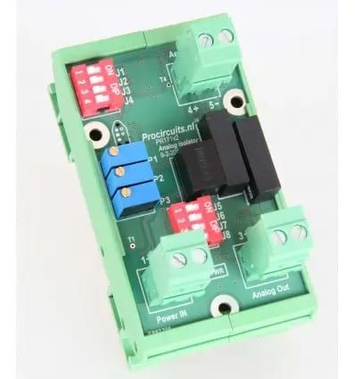
Article number PR171s01
The PR171s01 galvanically isolates analogue signals by means of an optocoupler, filters and amplifies them, and converts them to another industrial signal. Possible inputs are a 4-20 mA or 0-20 mA current loop, a potentiometer of 1 kΩ to 500 kΩ, 0-10 V, 0-5 V or -10 to +10 V; possible outputs are 4-20 mA, 0-20 mA, 0-10 V, -10 to +10 V or 0-200 mV. PWM and digital signals (2.5, 3.3 or 5 V) are also passed on with isolation, and the input and output levels may differ. The module is factory set to the range you specify; adjustments are made with trimmers P1, P2 and P3.
Price on request
Lead time on request. Not in stock? We will make it.
Orders are placed by email with a purchase order. We supply businesses only.
| Supply | 9 to 28 V DC |
|---|---|
| Input | 4-20 mA, 0-20 mA, potentiometer 1 kΩ to 500 kΩ, 0-10 V, 0-5 V, -10 to +10 V, PWM or digital (2.5, 3.3 or 5 V) |
| Output | 4-20 mA, 0-20 mA, 0-10 V, -10 to +10 V, 0-200 mV, PWM or digital (2.5, 3.3 or 5 V) |
| Isolation | Galvanic isolation between input and output by means of an optocoupler |
| Setup | Trimmers P1 (upper limit), P2 (lower limit) and P3 (negative offset) |
| Factory setting | Set to the range you specify when ordering |
A different input, another range, galvanic isolation or your own logo: we adapt the module.
You speak directly with the developer. Call or message Willem on +31 6 45 77 55 93.
PR171s01
Enter the quantity. You will receive price and lead time by email. You then order with a purchase order.
Send the article number and quantity via WhatsApp to +31 6 83 66 55 88. Willem replies on working days.
WhatsApp Willem(opens in a new tab)Signal converters
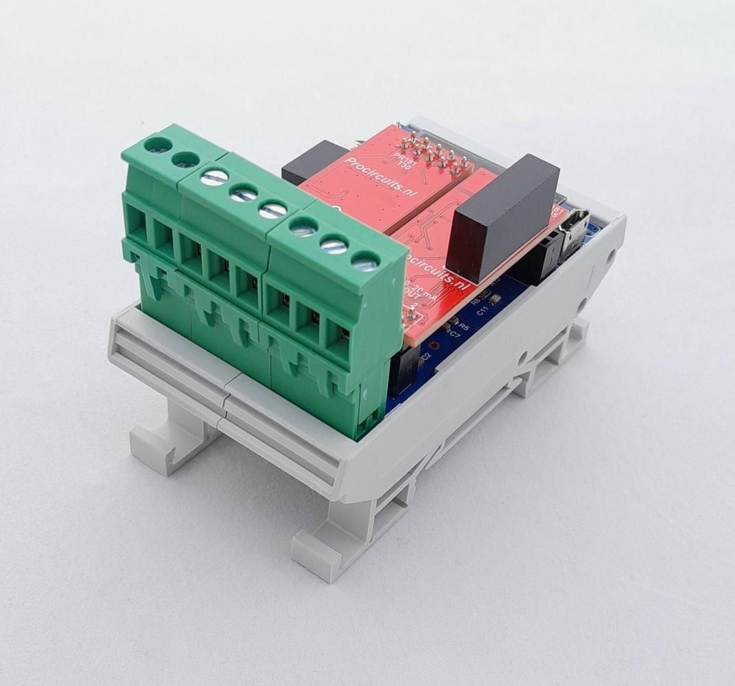
PR181-X091
In: 4-20 mA or 0-20 mAOut: 4-20 mA or 0-20 mA
PR181-X079
In: 0-10 VOut: 0-10 V
PR181x088
In: 4-20 mA or 0-20 mAOut: ±10 V
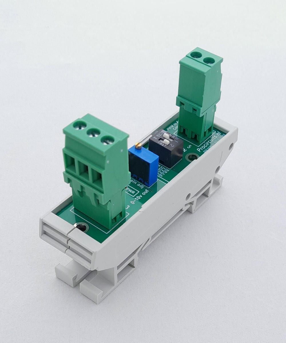
PR168
In: PWMOut: 0-10 V