Not quite right?
A different input, another range, galvanic isolation or your own logo: we adapt the module.


Article number PR168
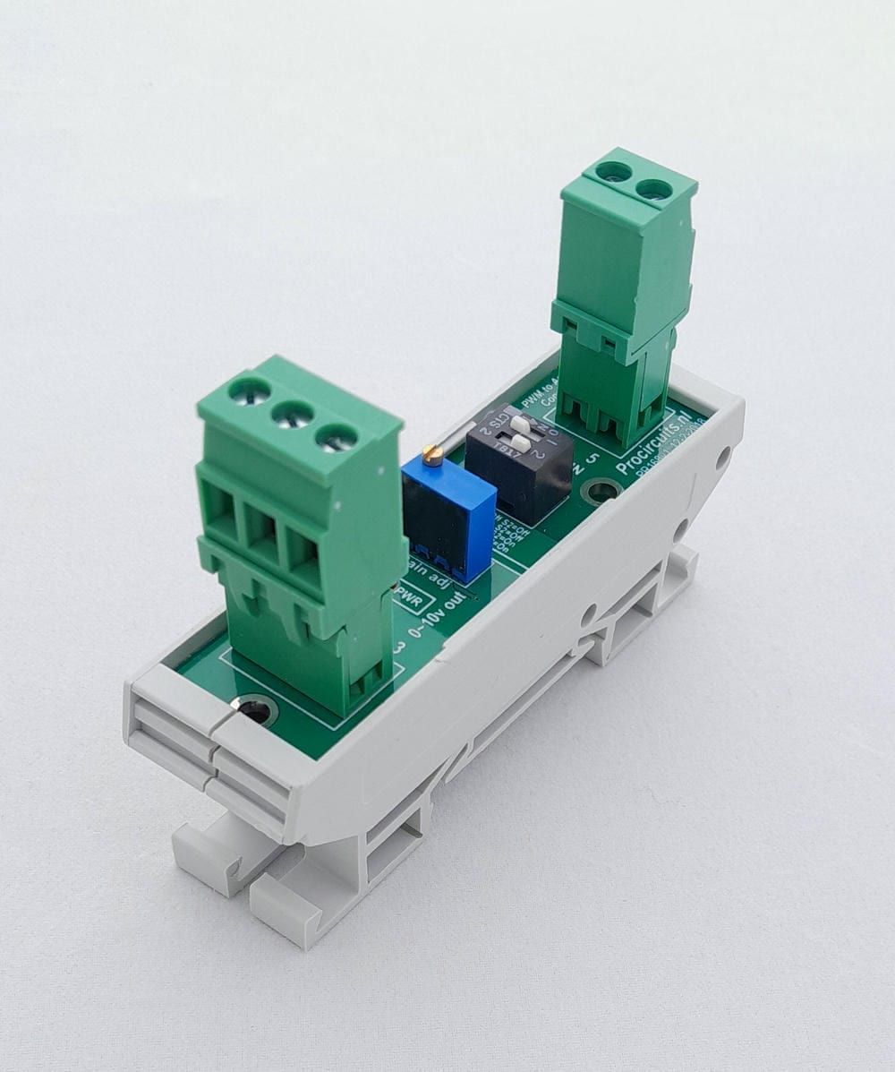
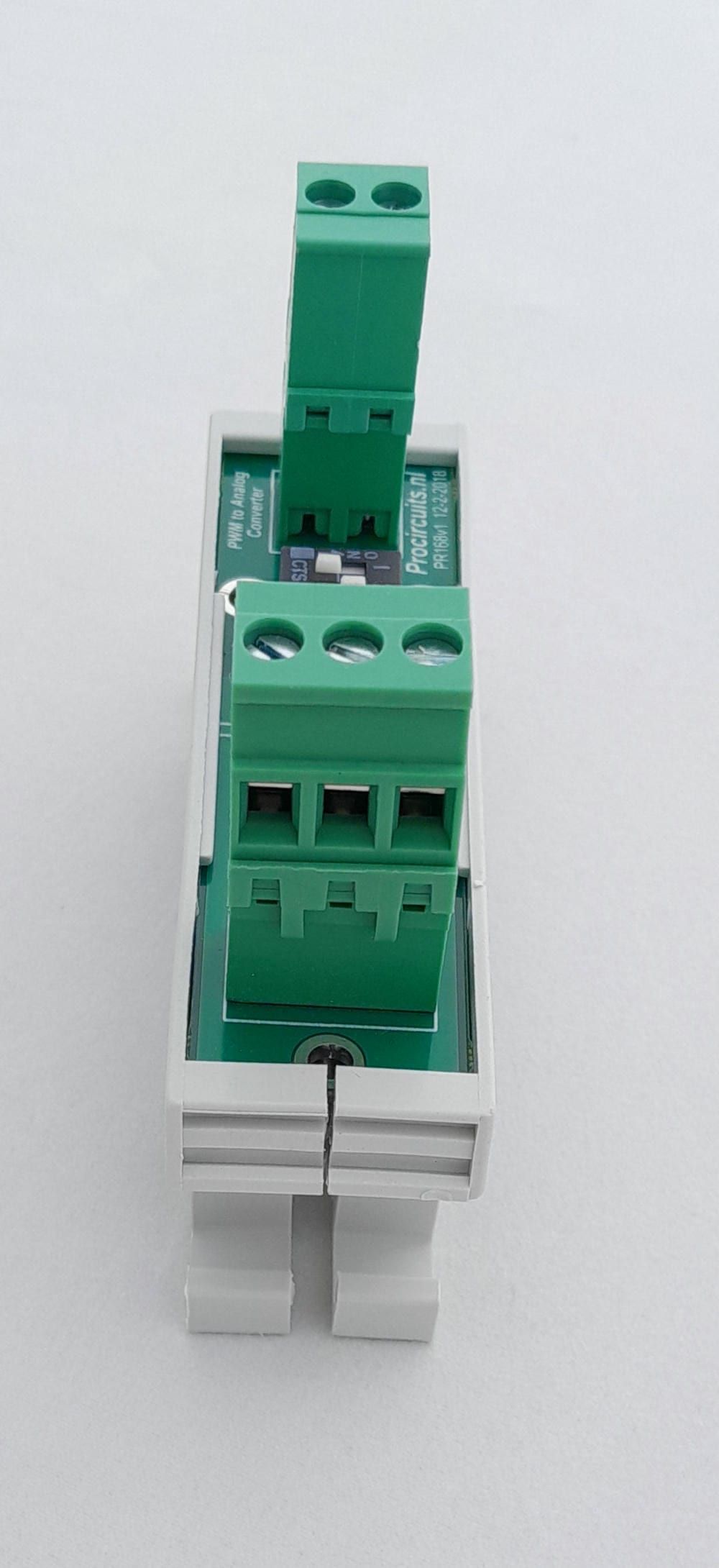
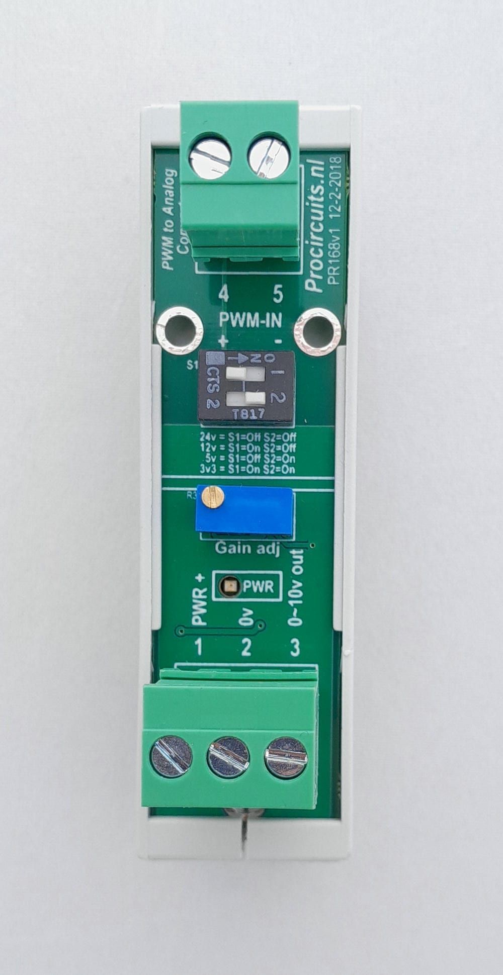
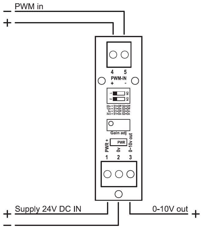
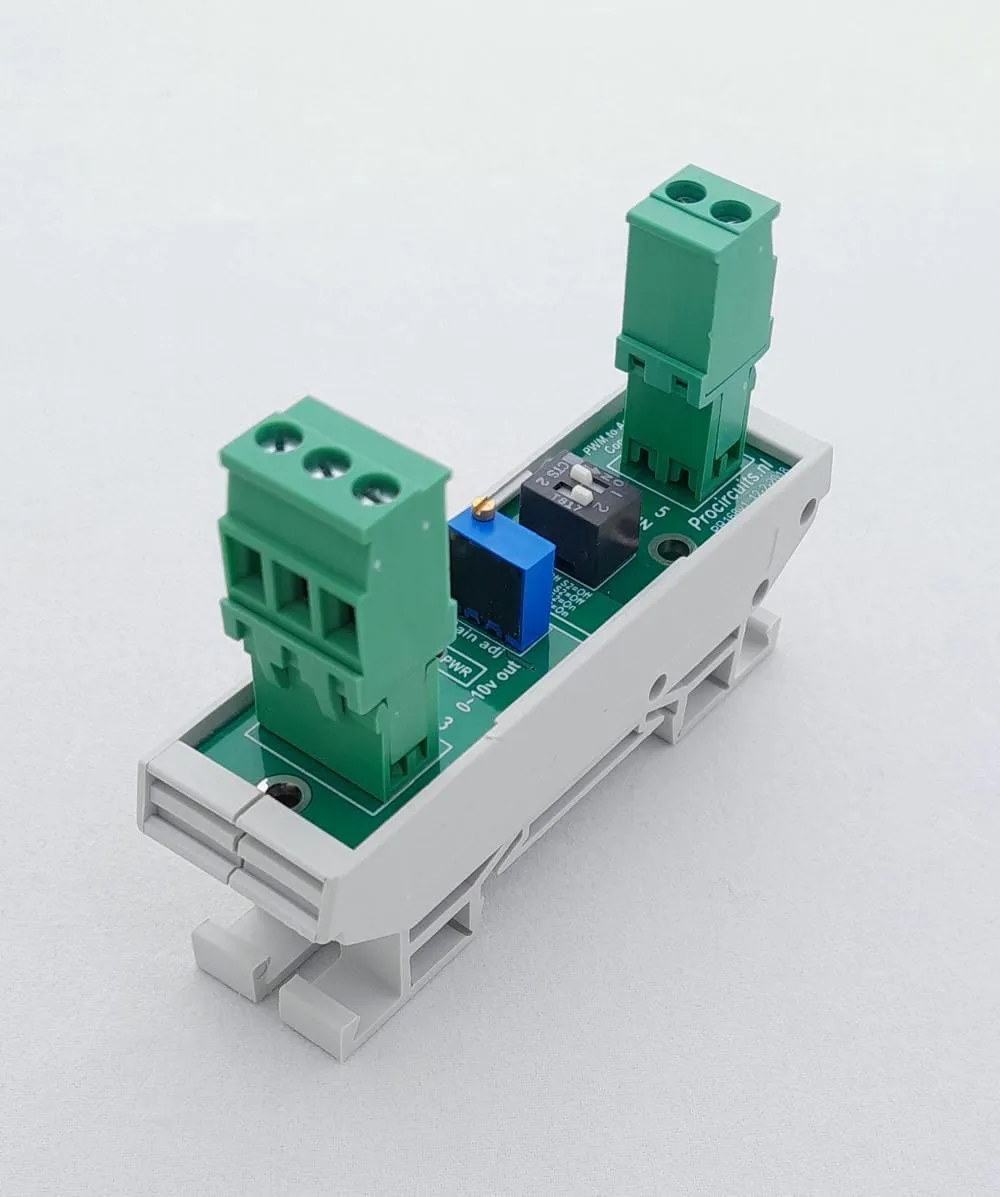
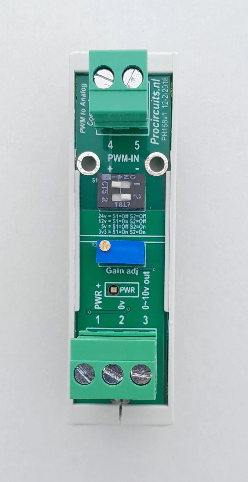
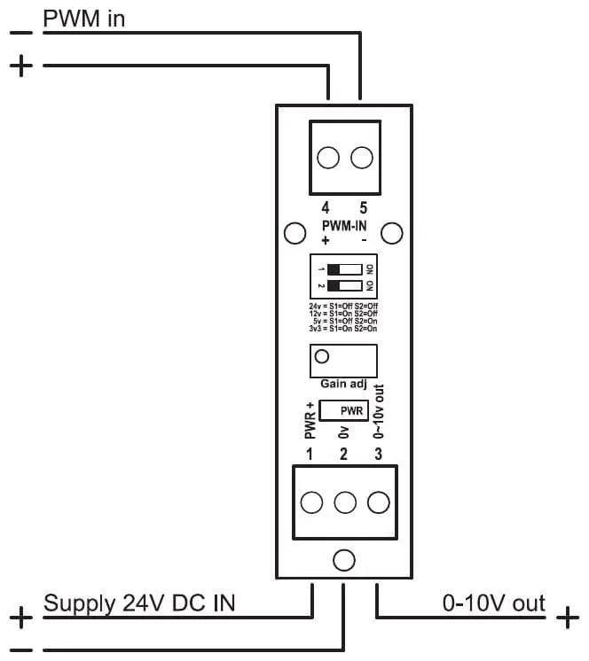
The PR168 converts a PWM signal into a 0-10 V analogue signal. The input is galvanically isolated from the output and the supply: this prevents ground loops, and the module reads both high-side and low-side switched PWM signals. DIP switches S1 and S2 select a PWM level of 3.3, 5, 12 or 24 V; the Gain adj trimmer adjusts the upper limit of the output. As delivered, 0 % duty cycle gives 0 V and 100 % duty cycle gives 10 V, for a 24 V PWM signal.
Price on request
Lead time on request. Not in stock? We will make it.
Orders are placed by email with a purchase order. We supply businesses only.
| Supply | 12 to 24 V DC |
|---|---|
| Input | PWM, 3.3 to 24 V; level 3.3, 5, 12 or 24 V selected with DIP switches S1 and S2 |
| Output | 0-10 V as delivered, 11 V max.; upper limit adjustable |
| Isolation | Input galvanically isolated from output and supply |
| Setup | DIP switches S1 and S2 for the input level, Gain adj trimmer for the upper limit |
| PWM frequency | 100 Hz to 5 kHz |
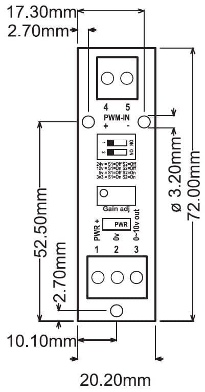
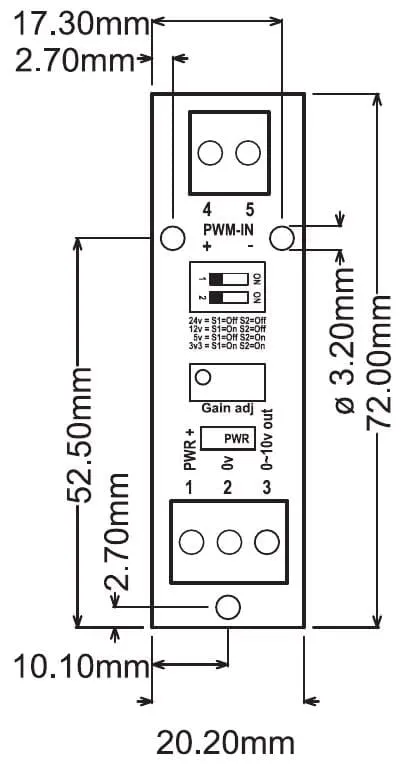
| Dimensions | 22.5 x 83 mm with DIN rail enclosure, 20 x 72 mm without |
| Factory setting | 24 V PWM signal; 0 % duty cycle = 0 V, 100 % duty cycle = 10 V |
| Terminal | Function |
|---|---|
| Terminal 1 | Supply plus, 12 or 24 V DC |
| Terminal 2 | Supply minus (0 V) |
| Terminal 3 | 0-10 V output (plus) |
| Terminal 4 | PWM input plus |
| Terminal 5 | PWM input minus |
A different input, another range, galvanic isolation or your own logo: we adapt the module.
You speak directly with the developer. Call or message Willem on +31 6 45 77 55 93.
PR168
Enter the quantity. You will receive price and lead time by email. You then order with a purchase order.
Send the article number and quantity via WhatsApp to +31 6 83 66 55 88. Willem replies on working days.
WhatsApp Willem(opens in a new tab)Signal converters
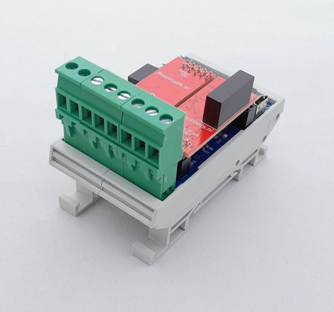
PR181-X074
In: PWMOut: 0-10 V
PR181-X008
In: PWMOut: 4-20 mA or 0-20 mA
PR181-X055
In: PWMOut: Relay
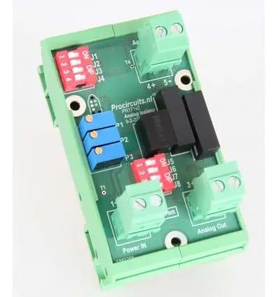
PR171s01
In: 4-20 mA, 0-20 mA, 0-10 V, 0-5 V, ±10 V, Potentiometer, PWM or DigitalOut: 4-20 mA, 0-20 mA, 0-10 V, ±10 V, PWM or Digital