Need a different combination?
We adapt an existing module or develop a new one. Ask Willem.


Reads up to 16 voltages, resistances or contacts via Modbus RS485, switches relays via CAN bus, and isolates or repeats an RS485 network.
No module with this combination. Ask about custom electronics
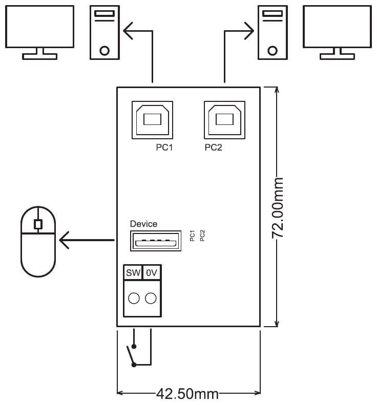
PR189
In: USB or DigitalOut: USB
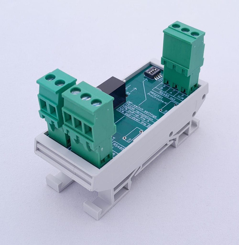
PR525x001
In: RS485Out: RS485
16-kanaals-spanningsmeting-Modbus
In: 0-5 V, 0-10 V or DigitalOut: Modbus
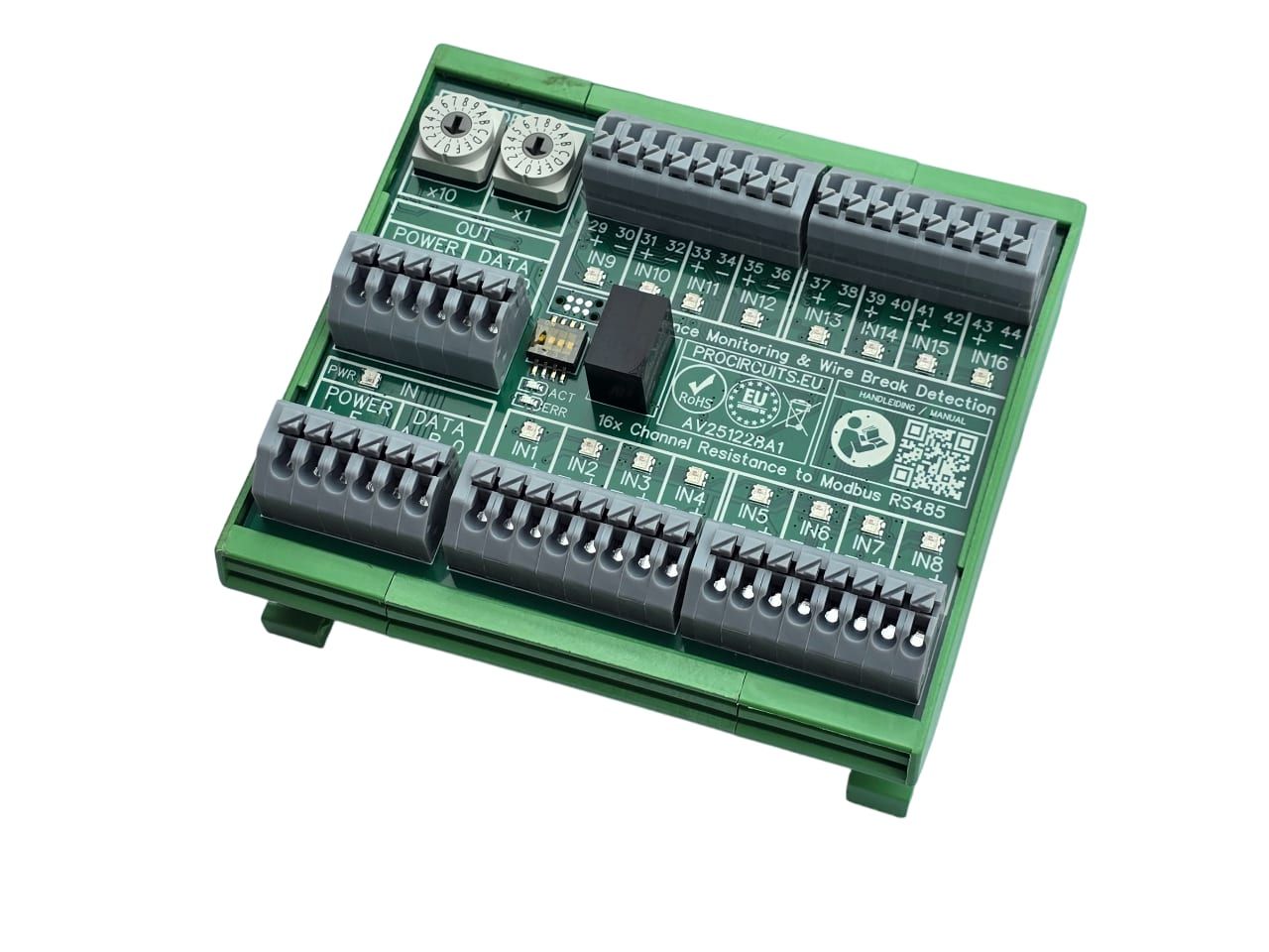
AV251228A1
In: ResistanceOut: Modbus
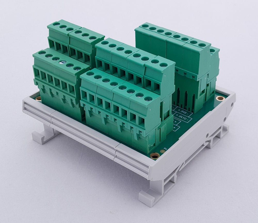
PR131s01
In: 0-10 V, 4-20 mA, Resistance, Potentiometer or DigitalOut: Modbus
PR131s02
In: Digital or ResistanceOut: Modbus
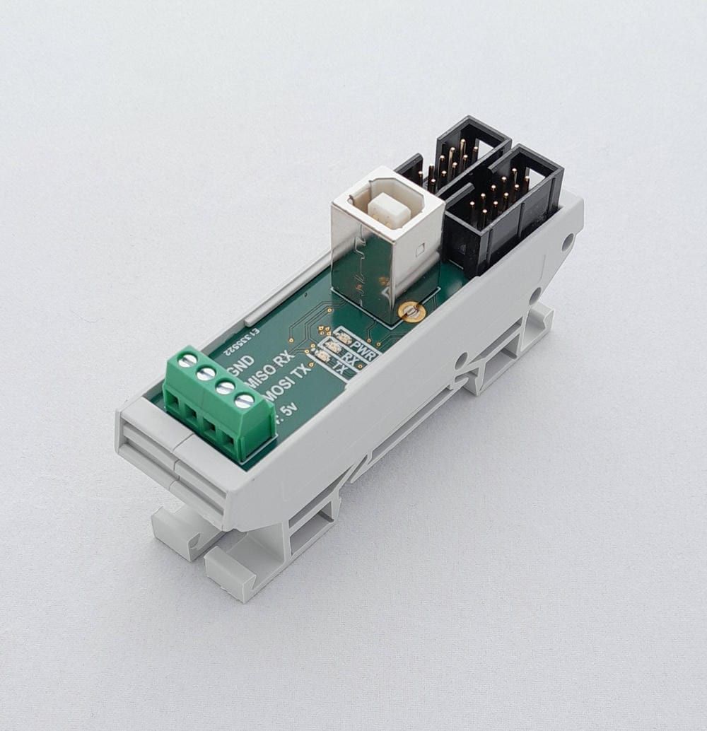
PR157s05
In: USB
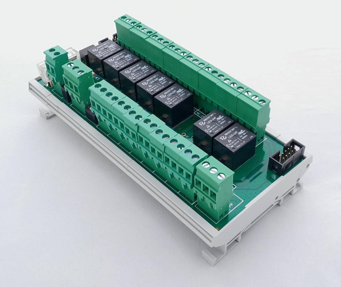
PR157s08
In: Digital, Potentiometer or CANOut: Relay or CAN
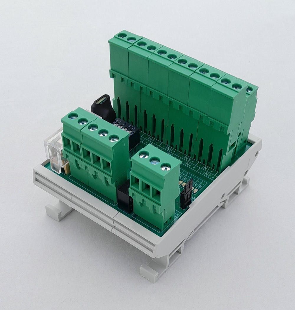
PR157s11
In: Digital or PotentiometerOut: CAN
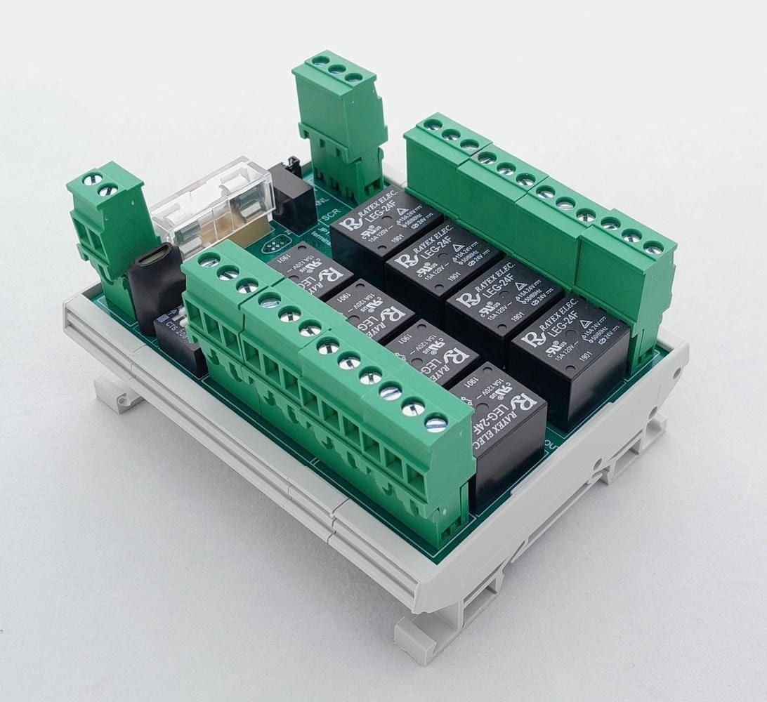
PR157s12
In: CANOut: Relay
We adapt an existing module or develop a new one. Ask Willem.
These measuring modules measure 16 inputs and place the values in Modbus registers, to be read via Modbus RTU over RS485 by a PLC, controller or SCADA system. The baud rate is adjustable from 9,600 to 921,600 bps, 19,200 bps on delivery. Supply 12 to 24 V DC (±15 %); dimensions with DIN rail enclosure 90 x 80 x 40 mm. On request: Modbus TCP over Ethernet, an isolated RS485 port, a different measuring range or a different input type.
The voltage module measures the voltage per channel, up to 24 V, for analogue and digital signals. The AV251228A1 measures the resistance per channel (0 Ω to 50 kΩ) and reports open circuit, short circuit and whether a button is pressed or released.
| Article | Input | Output |
|---|---|---|
| 16-kanaals-spanningsmeting-Modbus | 0-5 V, 0-10 V or Digital | Modbus |
| AV251228A1 | Resistance | Modbus |
The PR131 reads 16 inputs and passes the values on via Modbus RTU over RS485 (function codes 3 and 4). The slave address is set with two rotary switches. LEDs show power (PWR), communication (ACT) and errors (ERR). The module is protected against reverse polarity and overvoltage and has fuses. Supply 10 to 31 V DC, ambient temperature 0 to 55 °C, DIN rail mounting. A version with Modbus TCP over Ethernet is optional.
The PR131s01 is the general version for analogue and digital signals: 0-10 V, 4-20 mA, 0-30 V, resistances, potentiometers and contacts. The PR131s02 is set up to read the buttons of manual call points, reporting open circuits and short circuits; it is not a certified part of a fire alarm system.
| Article | Input | Output |
|---|---|---|
| PR131s01 | 0-10 V, 4-20 mA, Resistance, Potentiometer or Digital | Modbus |
| PR131s02 | Digital or Resistance | Modbus |
The PR157 series consists of DIN rail modules. The CAN bus versions read optically isolated 24 V inputs and a potentiometer, or switch relay outputs (24 V DC, 5 A) with separate NO, COM and NC terminals per output; status LEDs show the state of each input or output. Terminate both ends of the CAN bus network with 120 Ω: fit jumper JP1 on the module at the end of the network. More inputs or outputs, or control via RS485 and Modbus instead of CAN bus, are available on request for these versions.
| Article | Input | Output |
|---|---|---|
| PR157s05 | USB | – |
| PR157s08 | Digital, Potentiometer or CAN | Relay or CAN |
| PR157s11 | Digital or Potentiometer | CAN |
| PR157s12 | CAN | Relay |
Get in touch, without obligation
Contact