Not quite right?
A different input, another range, galvanic isolation or your own logo: we adapt the module.


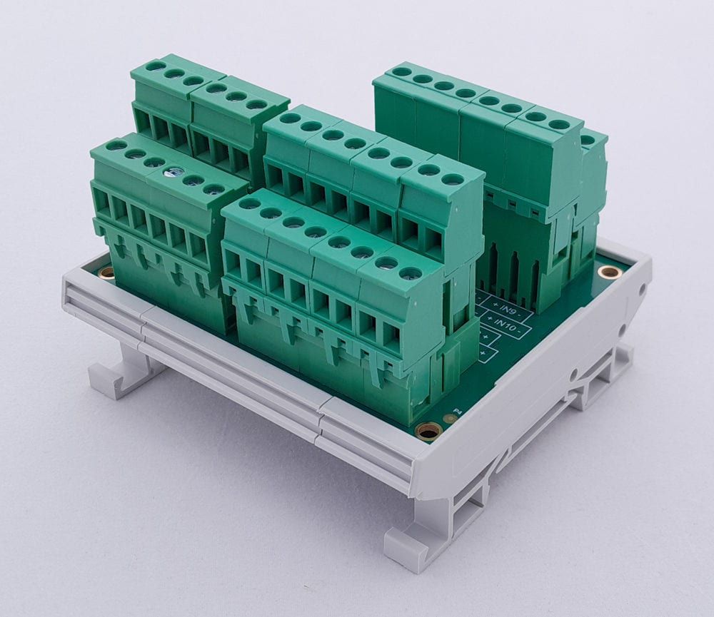
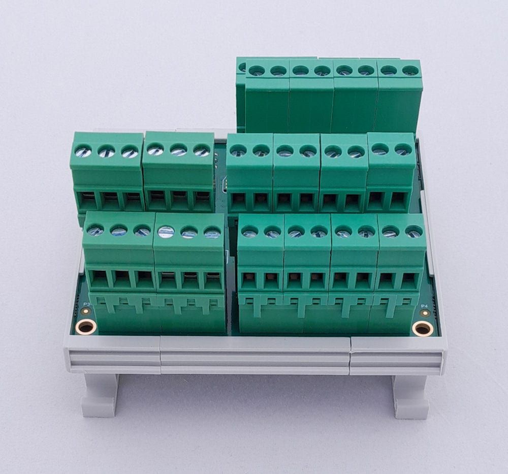
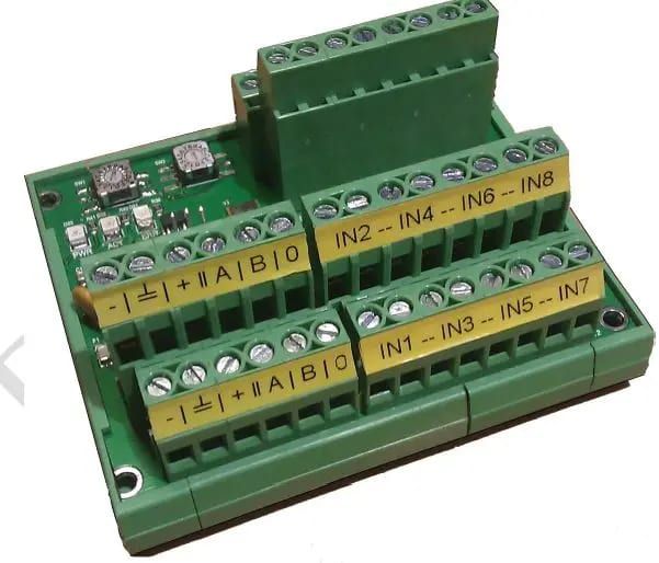
Article number PR131s02
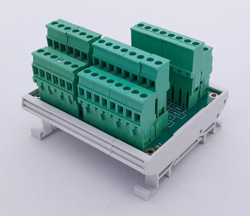
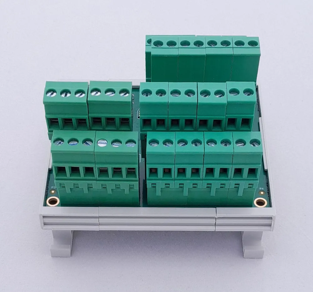
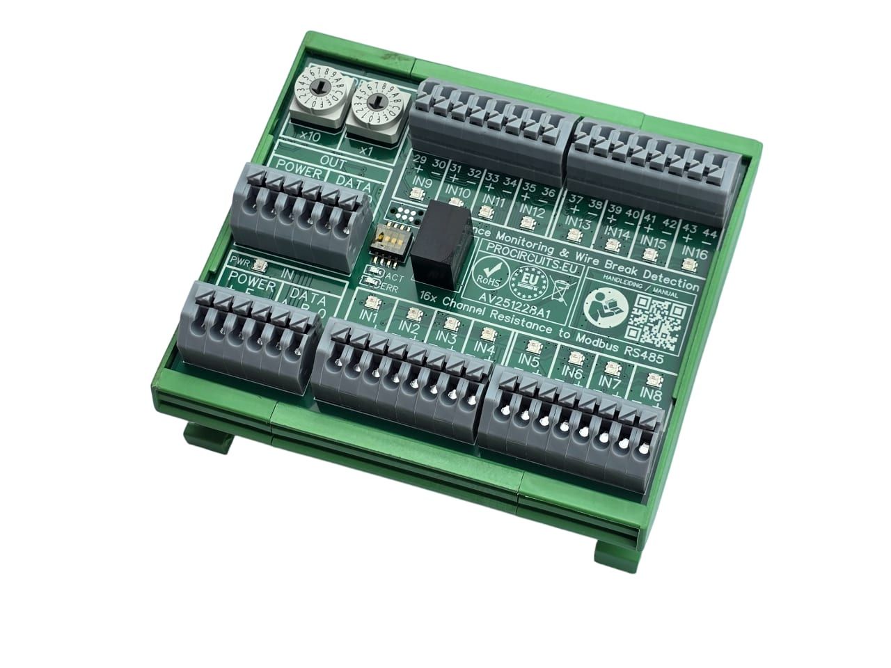
The PR131s02 is used to read the buttons of manual call points via Modbus. For each input it measures the line resistance and reports whether the button is pressed and whether there is an open circuit or a short circuit. Switches with or without an internal resistor are connected directly. The module is not a certified part of a fire alarm system.
Price on request
Lead time on request. Not in stock? We will make it.
Orders are placed by email with a purchase order. We supply businesses only.
| Supply | 10 to 31 V DC; ripple ±20 mV max. |
|---|---|
| Input | 16 analogue inputs for switches with or without an internal resistor |
| Output | Modbus RTU over RS485, function codes 3 (holding registers) and 4 (input registers); Modbus TCP over Ethernet optional |
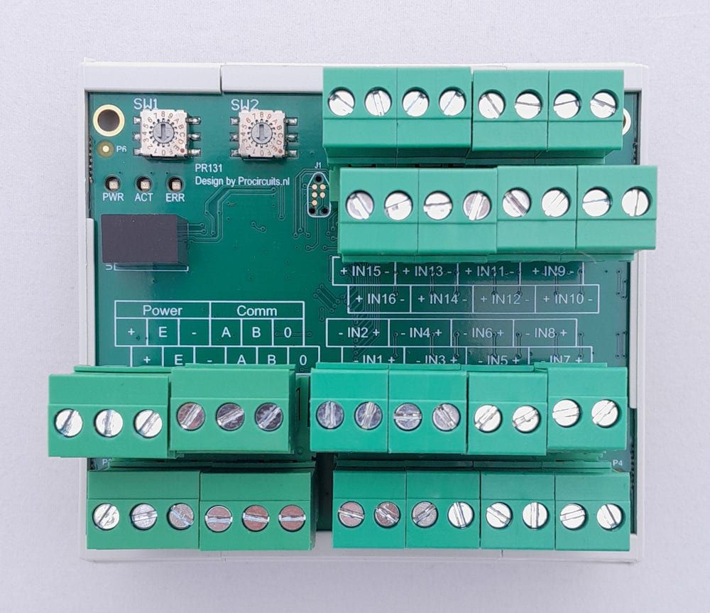
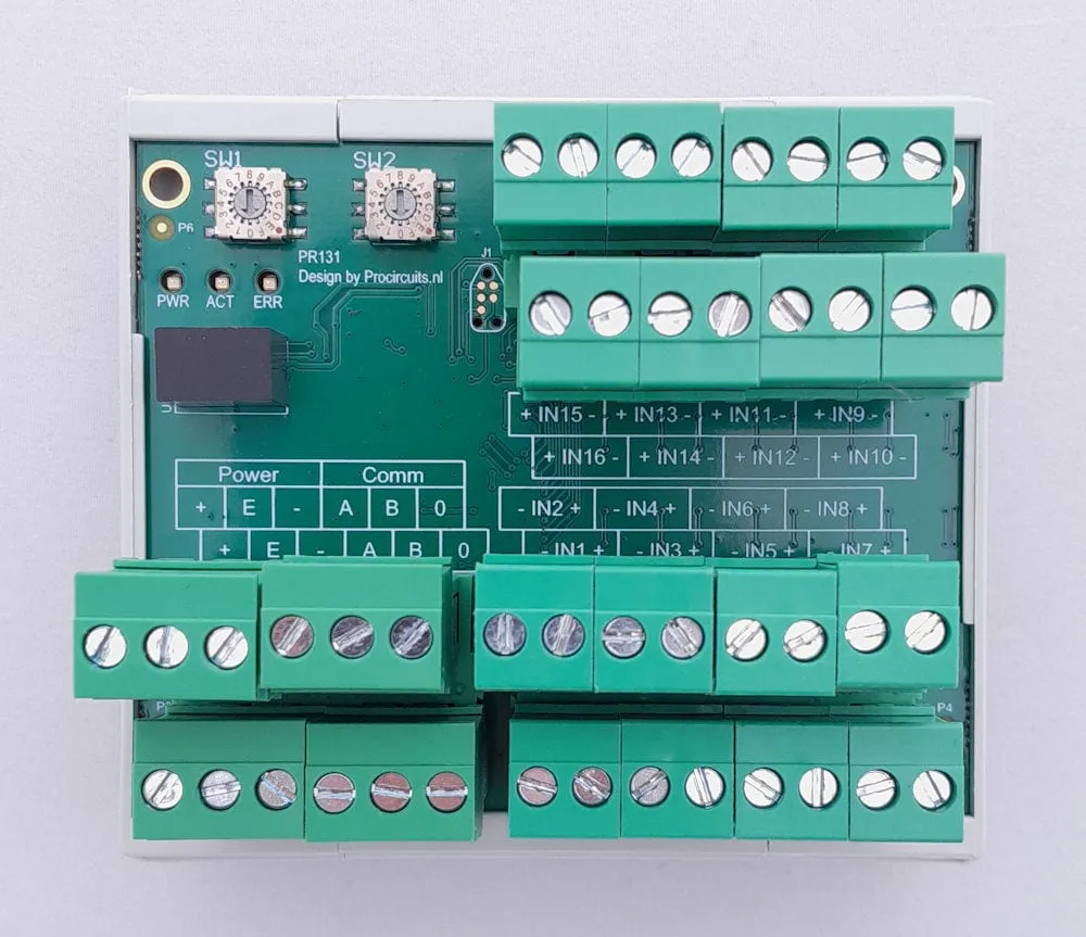
| Setup | Slave address with two rotary switches: SW1 (tens) and SW2 (units) |
| Modbus settings | 19,200 baud, 1 stop bit, no parity |
| Read-out per input | Register 1 input open (line resistance > 2.6 kΩ), register 2 input closure (< 20 Ω), register 3 status A (active at 420 to 520 Ω, inactive at 840 to 1030 Ω), register 4 status B (contact closed, < 20 Ω); tolerance ±5 % |
| Protection | Reverse polarity protection, overvoltage protection, earth fault detection and fuses on the supply |
| Indication | LEDs PWR (power), ACT (communication) and ERR (error) |
| Ambient temperature | 0 to 55 °C |
| Mounting | DIN rail; screw terminals for wire up to 3 mm² |
| Terminal | Function |
|---|---|
| Terminal Power + | Supply plus |
| Terminal Power E | Earth |
| Terminal Power - | Supply minus |
| Terminal Comm A | RS485 A |
| Terminal Comm B | RS485 B |
| Terminal Comm 0 | RS485 0 V |
| Terminal IN1 – IN16 | Inputs 1 to 16, a plus and a minus terminal per input |
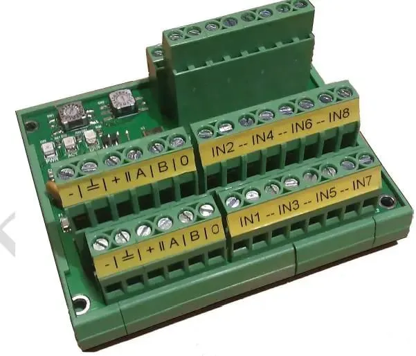
The PR131 reads 16 inputs and passes the values on via Modbus RTU over RS485 (function codes 3 and 4). The slave address is set with two rotary switches. LEDs show power (PWR), communication (ACT) and errors (ERR). The module is protected against reverse polarity and overvoltage and has fuses. Supply 10 to 31 V DC, ambient temperature 0 to 55 °C, DIN rail mounting. A version with Modbus TCP over Ethernet is optional.
The PR131s01 is the general version for analogue and digital signals: 0-10 V, 4-20 mA, 0-30 V, resistances, potentiometers and contacts. The PR131s02 is set up to read the buttons of manual call points, reporting open circuits and short circuits; it is not a certified part of a fire alarm system.
A different input, another range, galvanic isolation or your own logo: we adapt the module.
You speak directly with the developer. Call or message Willem on +31 6 45 77 55 93.
PR131s02
Enter the quantity. You will receive price and lead time by email. You then order with a purchase order.
Send the article number and quantity via WhatsApp to +31 6 83 66 55 88. Willem replies on working days.
WhatsApp Willem(opens in a new tab)I/O modules
PR131s01
In: 0-10 V, 4-20 mA, Resistance, Potentiometer or DigitalOut: Modbus
AV251228A1
In: ResistanceOut: Modbus
16-kanaals-spanningsmeting-Modbus
In: 0-5 V, 0-10 V or DigitalOut: Modbus
PR525x001
In: RS485Out: RS485