Not quite right?
A different input, another range, galvanic isolation or your own logo: we adapt the module.


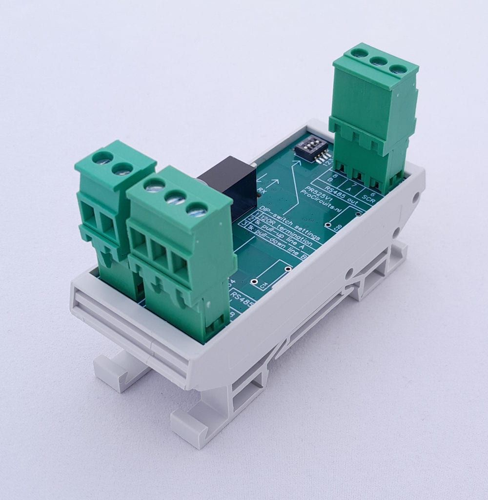
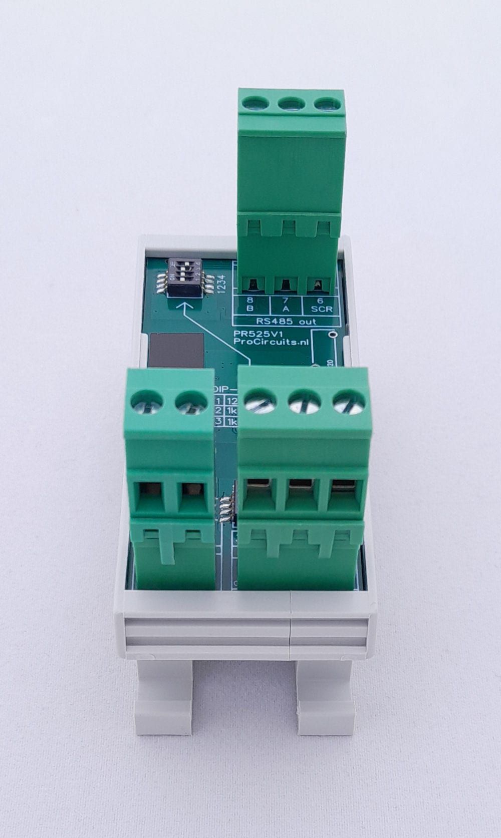
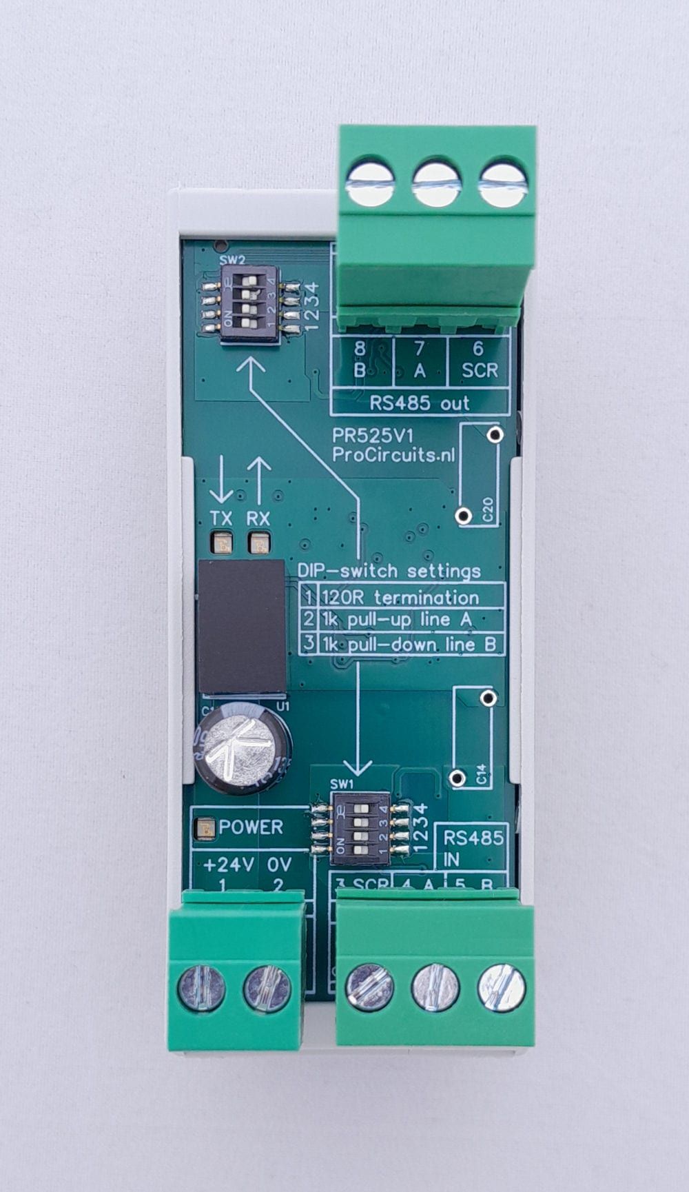
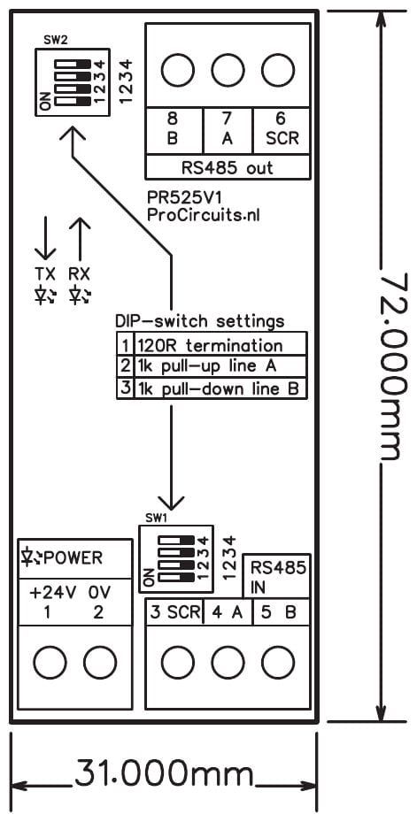
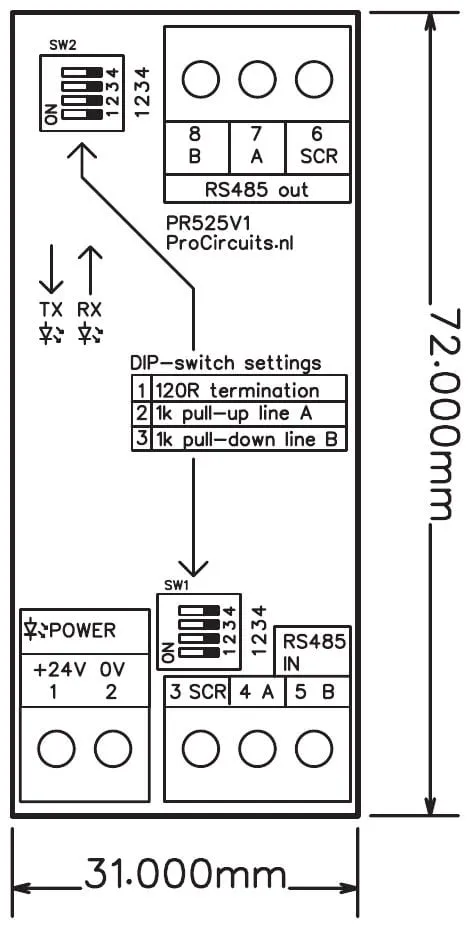
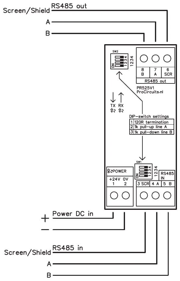
Article number PR525x001
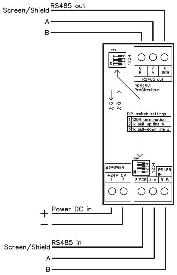
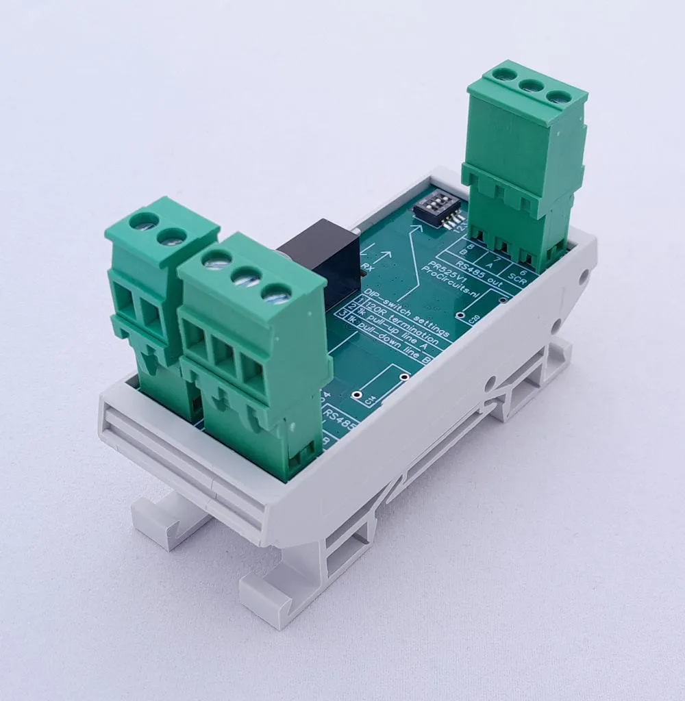
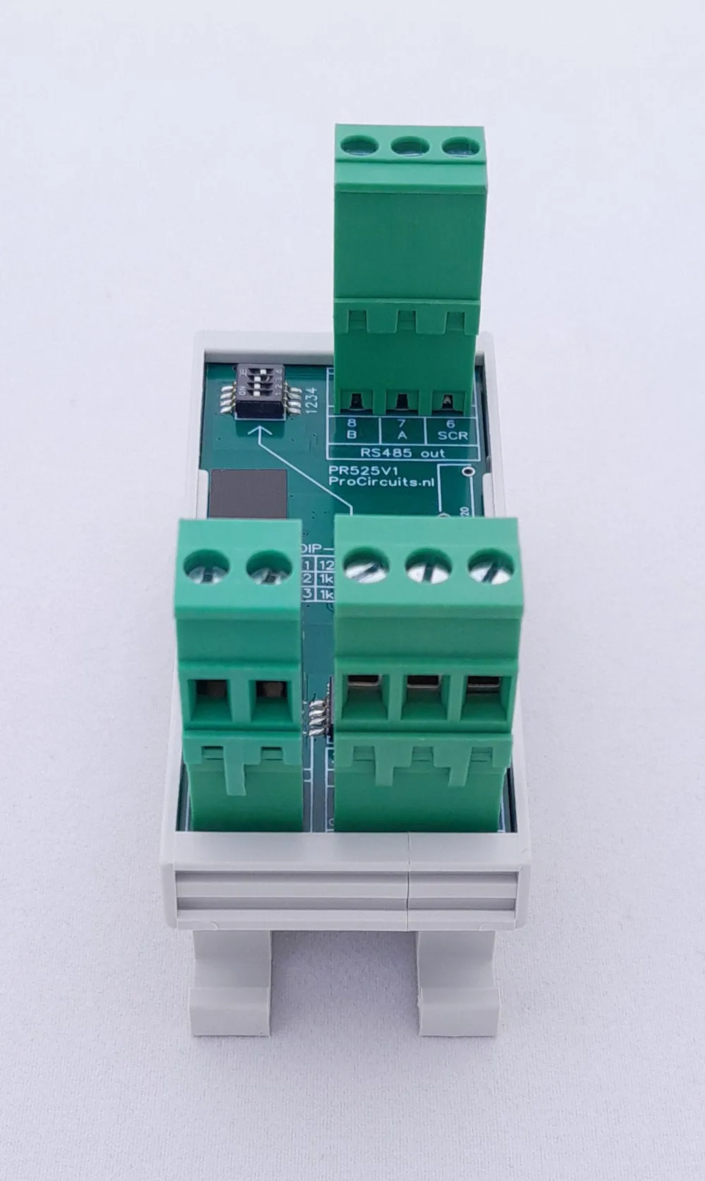
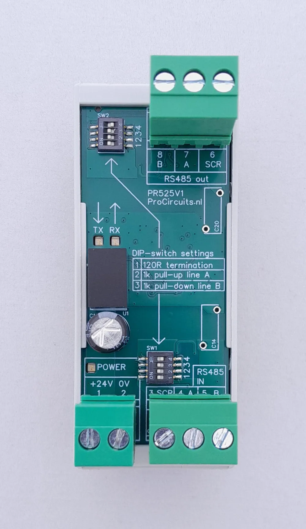
This isolator and repeater breaks ground loops in an RS485 or Modbus network. Placed at the right points, it allows longer cables or higher data rates. Input and output are galvanically isolated from each other and from the supply, which can be 12 or 24 V DC. The termination resistor and the pull-up and pull-down resistors are enabled per side with DIP switches.
Price on request
Lead time on request. Not in stock? We will make it.
Orders are placed by email with a purchase order. We supply businesses only.
| Supply | 9 to 30 V DC, for 12 and 24 V systems |
|---|---|
| Input | RS485 (A, B and shield) |
| Output | RS485 (A, B and shield), repeated |
| Isolation | Input, output and supply galvanically isolated from each other |
| Setup | DIP switches SW1 (input) and SW2 (output): 120 Ω termination resistor, 1 kΩ pull-up to 5 V on line A, 1 kΩ pull-down to 0 V on line B |
| Baud rate | 500,000 baud max. |
| Indication | POWER, TX and RX LEDs |
| Dimensions | 34 x 83 mm with DIN rail enclosure, 31 x 72 mm without |
| Mounting | DIN rail |
| Terminal | Function |
|---|---|
| Terminal 1 | Supply plus |
| Terminal 2 | Supply 0 V |
| Terminal 3 | Shield of the incoming RS485 cable (SCR) |
| Terminal 4 | Incoming RS485, signal A |
| Terminal 5 | Incoming RS485, signal B |
| Terminal 6 | Shield of the outgoing RS485 cable (SCR) |
| Terminal 7 | Outgoing RS485, signal A |
| Terminal 8 | Outgoing RS485, signal B |
A different input, another range, galvanic isolation or your own logo: we adapt the module.
You speak directly with the developer. Call or message Willem on +31 6 45 77 55 93.
PR525x001
Enter the quantity. You will receive price and lead time by email. You then order with a purchase order.
Send the article number and quantity via WhatsApp to +31 6 83 66 55 88. Willem replies on working days.
WhatsApp Willem(opens in a new tab)I/O modules
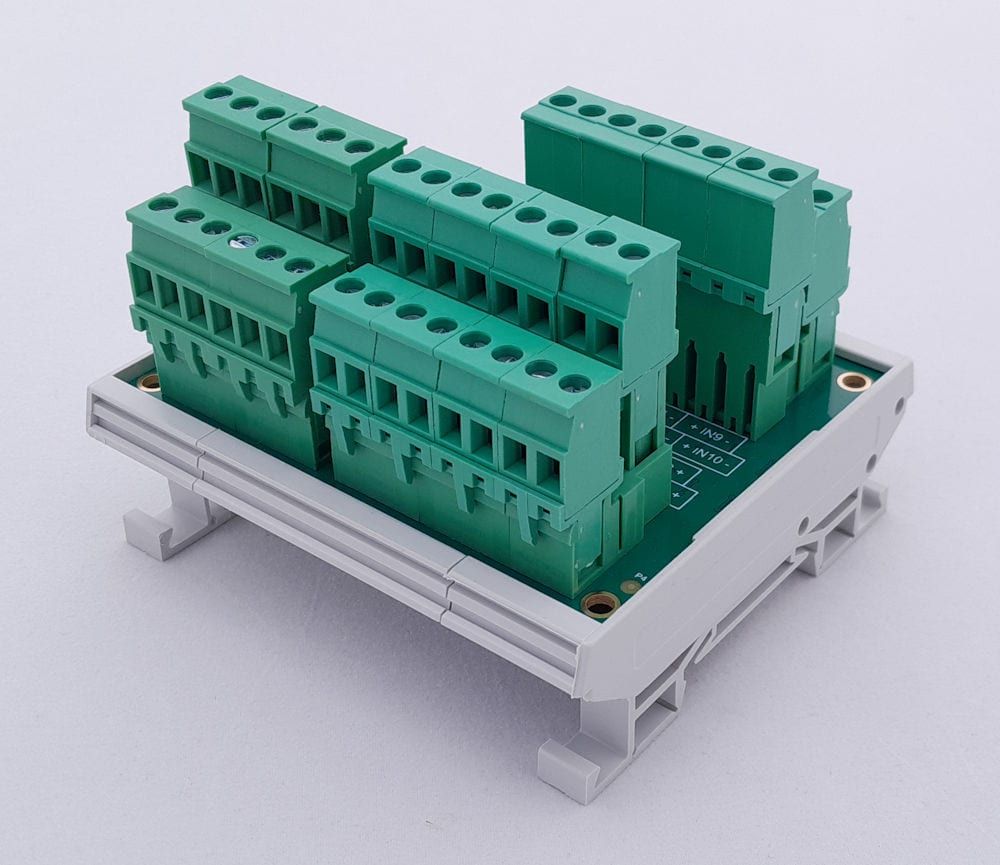
PR131s01
In: 0-10 V, 4-20 mA, Resistance, Potentiometer or DigitalOut: Modbus
PR131s02
In: Digital or ResistanceOut: Modbus
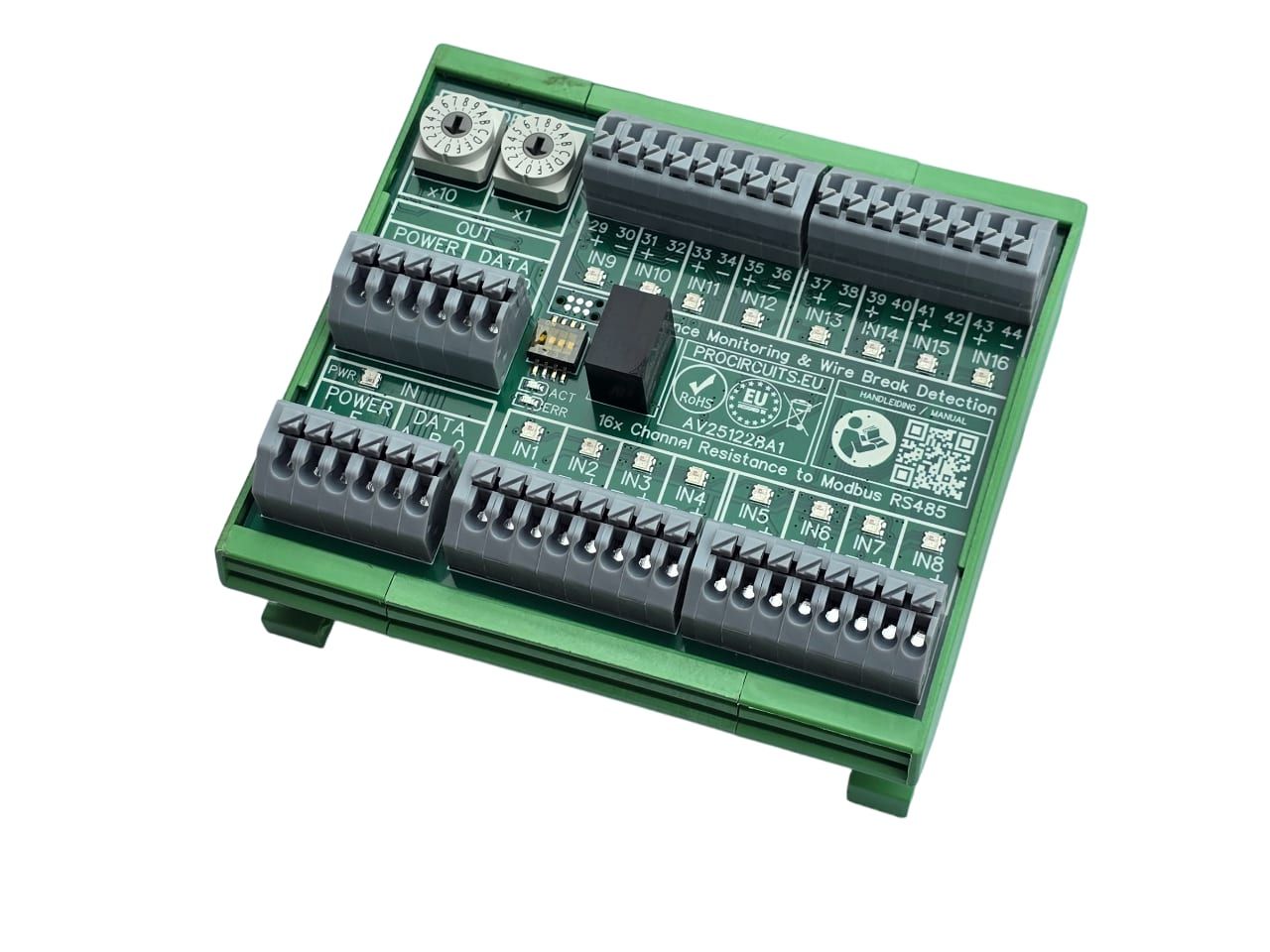
AV251228A1
In: ResistanceOut: Modbus
16-kanaals-spanningsmeting-Modbus
In: 0-5 V, 0-10 V or DigitalOut: Modbus