Not quite right?
A different input, another range, galvanic isolation or your own logo: we adapt the module.


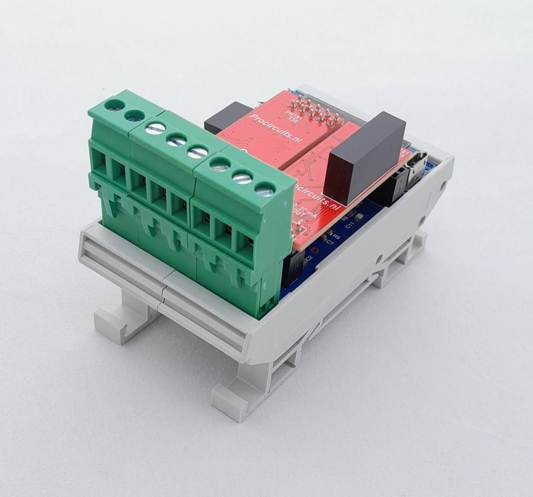
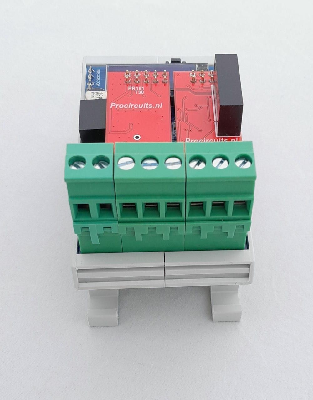
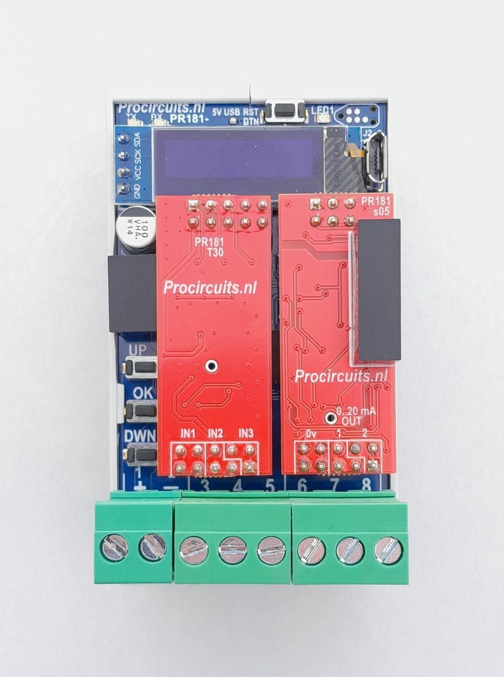
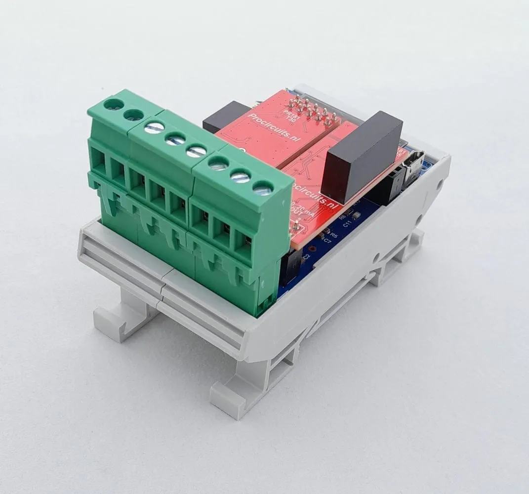
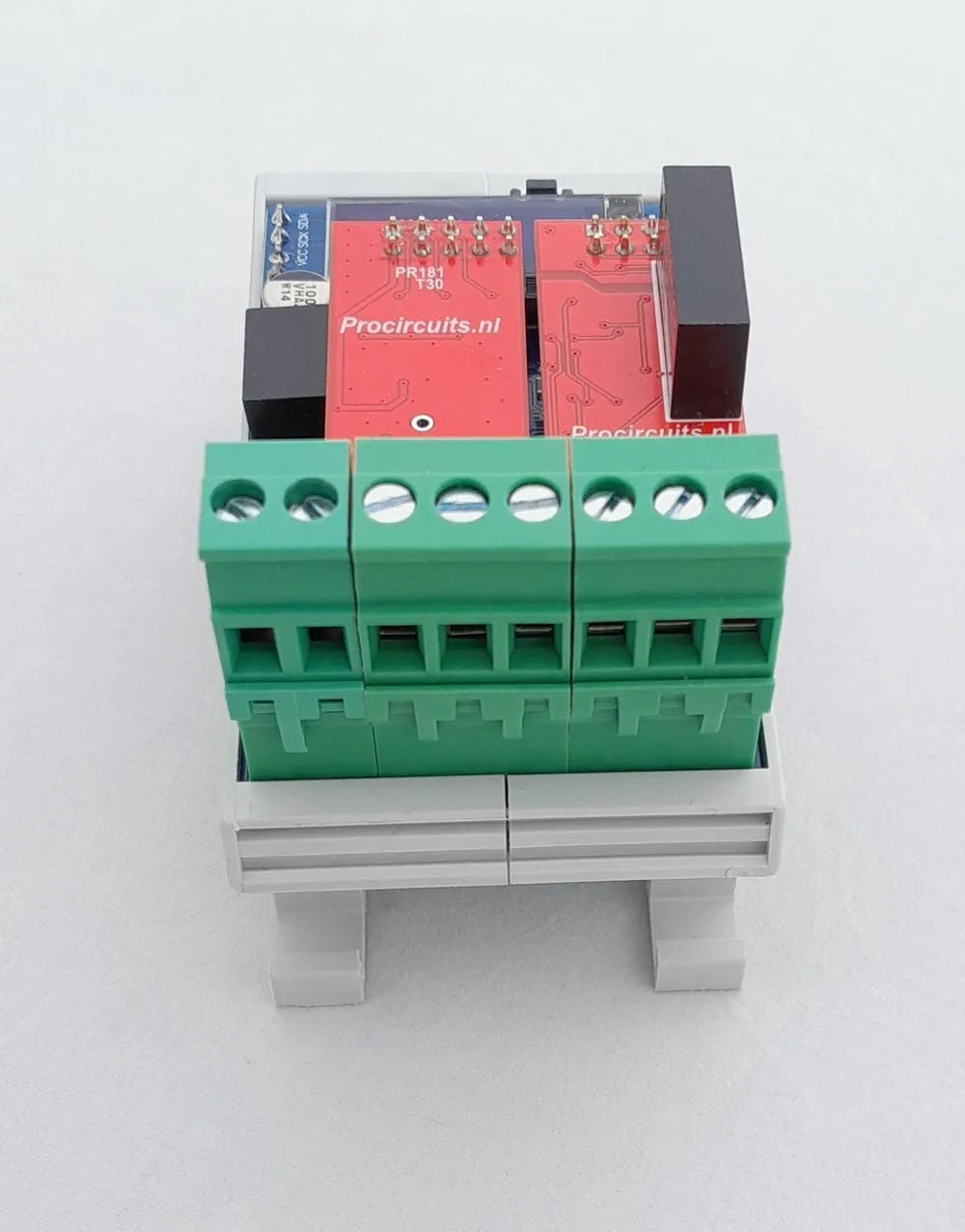
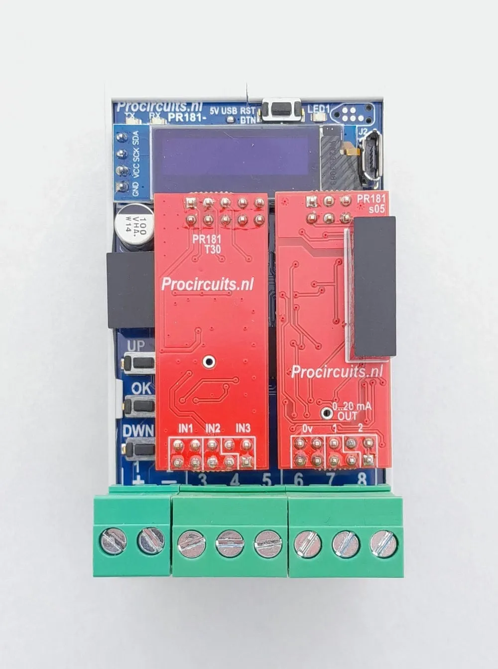
Article number PR181-X046
The PR181-X046 converts a centre-position joystick or potentiometer into a 4-20 mA signal. As delivered, the output gives 4 mA in the centre position and 20 mA at the far left and far right. The left, centre and right positions, the dead band around the centre and the output limits are set on the display. An adjustable delay in the neutral position prevents the drive from going straight from forward to reverse, so that clutch and motor are not subjected to shocks.
Price on request
Lead time on request. Not in stock? We will make it.
Orders are placed by email with a purchase order. We supply businesses only.
| Supply | 9 to 30 V DC |
|---|---|
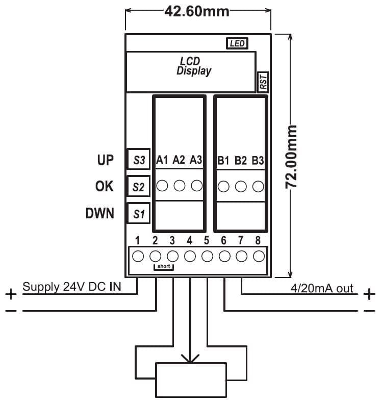
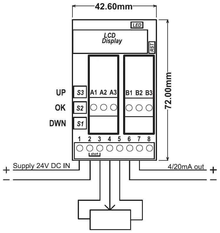
| Input | Centre-position joystick or potentiometer on terminals 3, 4 and 5 |
| Output | 4-20 mA as delivered, 21 mA max.; lower and upper limit adjustable |
| Isolation | Output galvanically isolated from input and supply |
| Setup | Display with UP, OK and DOWN buttons |
| Rise and fall rate | Adjustable on the display |
| Centre position | Dead band and neutral delay adjustable on the display |
| Ambient temperature | -25 to 55 °C, non-condensing |
| Dimensions | 45 x 83 mm with DIN rail enclosure, 42.6 x 72 mm without |
| Factory setting | Joystick left = 20 mA, centre = 4 mA, right = 20 mA |
| Terminal | Function |
|---|---|
| Terminal 1 | Supply plus |
| Terminal 2 | Supply minus |
| Terminal 3 | Joystick minus, internally connected to terminal 2 |
| Terminal 4 | Joystick signal (wiper) |
| Terminal 5 | Joystick plus |
| Terminal 6 | Isolated output common |
| Terminal 7 | Isolated 4-20 mA output (plus) |
| Terminal 8 | Not used |
The modules in the PR181 series are set up on the display on the module, using the UP, DOWN and OK buttons. On most versions the lower and upper limits of input and output are set independently, as is the rise and fall rate of the output; the settings of each module are listed on the product page under Setup. With an adjustable rise and fall rate, motors, pumps, valves and hydraulics can be driven smoothly. On versions with an analogue output, that output is galvanically isolated from input and supply to prevent ground loops. New settings are stored through the SAVE menu. The standard DIN rail enclosure measures 45 x 83 mm (board 42.6 x 72 mm); versions with more terminals are wider. Most modules run on 9 to 30 V DC at -25 to 55 °C, non-condensing.
For some conversions there is also a version without display and without galvanic isolation in the PR100 series: it is set up with push buttons and runs on 12 and 24 V DC (operating range 11 to 30 V DC). Where one exists, it is listed on the product page under Other version.
A different input, another range, galvanic isolation or your own logo: we adapt the module.
You speak directly with the developer. Call or message Willem on +31 6 45 77 55 93.
PR181-X046
Enter the quantity. You will receive price and lead time by email. You then order with a purchase order.
Send the article number and quantity via WhatsApp to +31 6 83 66 55 88. Willem replies on working days.
WhatsApp Willem(opens in a new tab)Potentiometers
PR181-X089
In: PotentiometerOut: 4-20 mA or 0-20 mA
PR181-X067
In: PotentiometerOut: 0-10 V
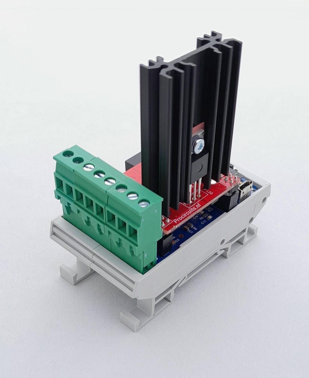
PR181-X052
In: Joystick or 0-10 VOut: PWM
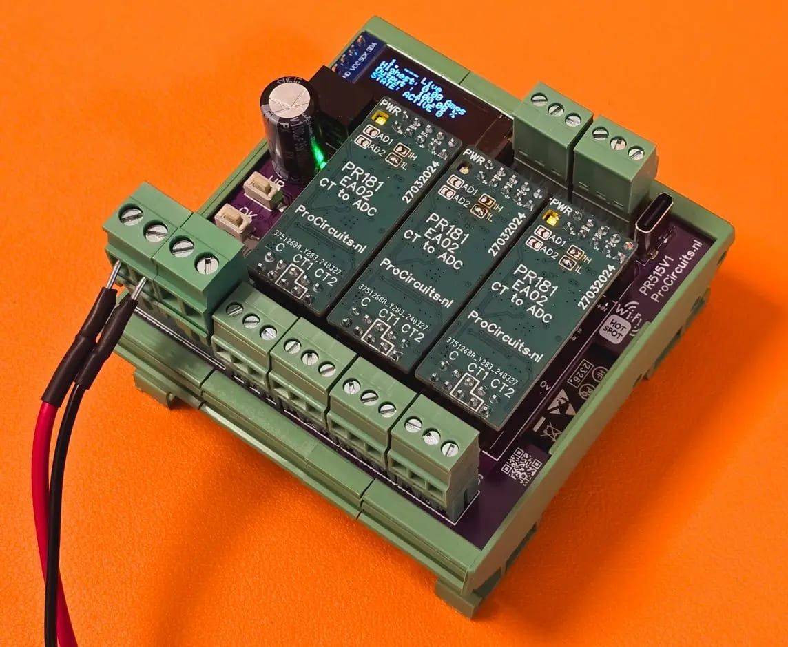
PR515x016
In: 4-20 mA or RS485Out: PWM