Not quite right?
A different input, another range, galvanic isolation or your own logo: we adapt the module.


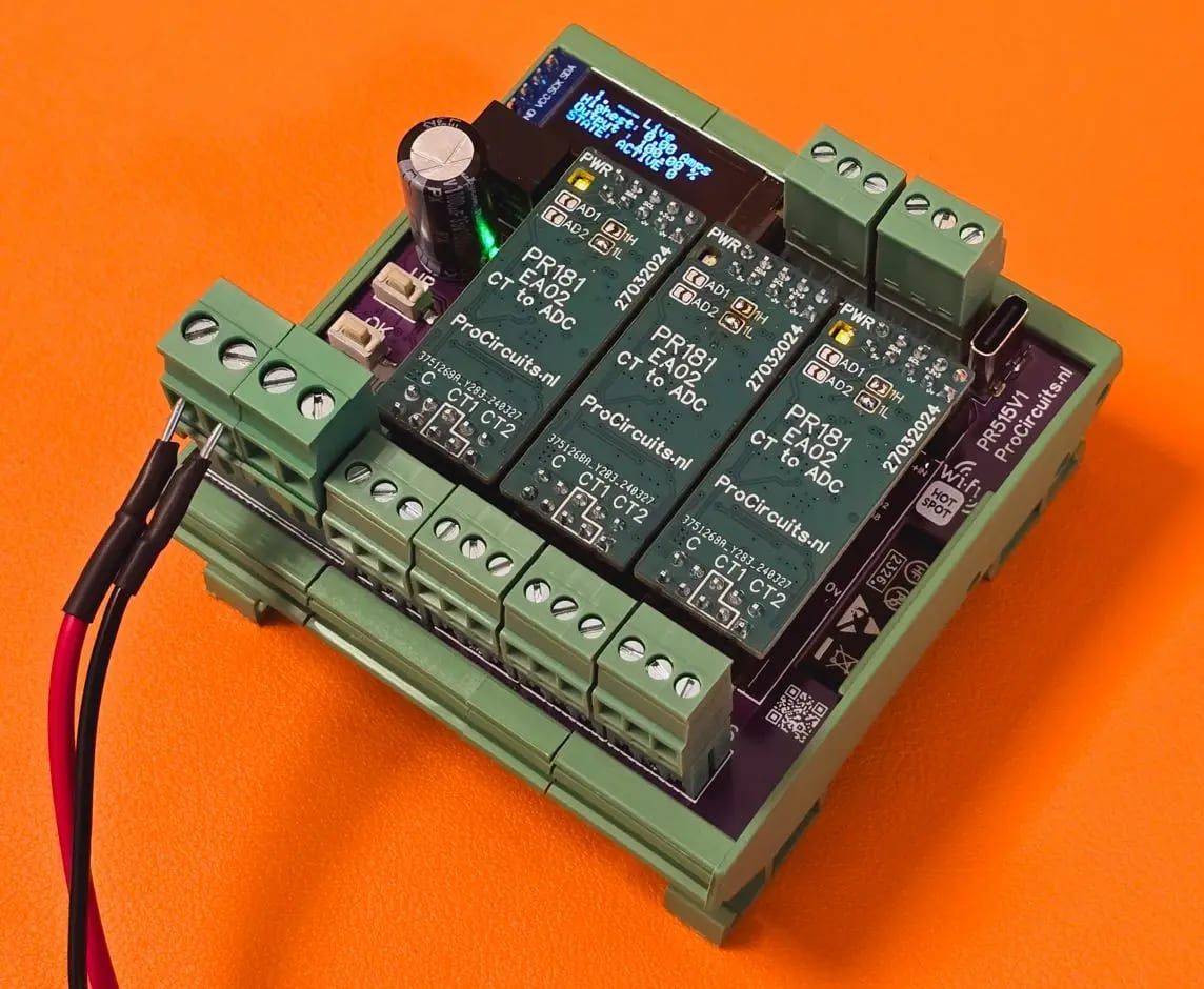
Article number PR515x016
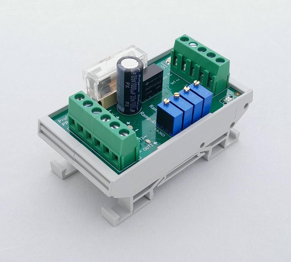
The PR515x016 compares a 4-20 mA set point, for example from a joystick, with the actual position of an encoder on a galvanically isolated RS485/RS422 link. Based on the difference, the built-in PID controller drives the motor outputs for anticlockwise and clockwise, switched or proportional with PWM, with adjustable ramp-up and ramp-down to spare the mechanics. Open circuit and short circuit on the 4-20 mA input and faults in the encoder communication are detected; the outputs then switch off. The module is set up over Wi-Fi in a browser, and the OLED display shows position, input and outputs.
Price on request
Lead time on request. Not in stock? We will make it.
Orders are placed by email with a purchase order. We supply businesses only.
| Supply | 10 to 32 V DC |
|---|---|
| Consumption | Approx. 2 W |
| Input | Set point 4-20 mA on terminal 12, range adjustable (for example 0-20 mA or 5-18 mA) |
| Output | H-bridge with two outputs: terminal 3 anticlockwise, terminal 4 clockwise (plus when active, minus when inactive), switched or PWM |
| Isolation | RS485/RS422 encoder link galvanically isolated; 4-20 mA input and outputs not isolated |
| Setup | Over Wi-Fi in a browser; Wi-Fi is switched on in the OLED menu |
| Encoder | Encoder with RS485/RS422 link (4-wire), on terminals 9 and 10 |
| Control | PID controller with adjustable Kp and Kd; hysteresis and dead band adjustable |
| PWM frequency | Adjustable, best between 100 and 250 Hz |
| Rise and fall rate | Ramp-up and ramp-down time adjustable in ms |
| Monitoring | Open circuit and short circuit on the 4-20 mA input and the encoder communication; outputs off on a fault |
| Use | Not a safety system: provide fail-safe measures that work independently of the module |
| Dimensions | 79.5 x 58 x 82 mm (w x d x h) |
| Mounting | DIN rail; screw terminals, USB-C for firmware and diagnostics |
| Terminal | Function |
|---|---|
| Terminal 1 | Supply plus, 10 to 32 V DC |
| Terminal 2 | Supply minus |
| Terminal 3 | Motor output anticlockwise (plus when active, minus when inactive) |
| Terminal 4 | Motor output clockwise (plus when active, minus when inactive) |
| Terminal 9 | Encoder Data- (green wire) |
| Terminal 10 | Encoder Data+ (yellow wire) |
| Terminal 12 | 4-20 mA set point (signal); connect the source minus to the supply minus |
The modules in the PR515 series have an OLED display and push buttons, so they can be set up without a computer and show the current values of inputs and outputs. They run on 12 and 24 V DC systems. Most versions can be extended on request, for example with an extra relay output, a PWM output, a bus connection (CAN bus or Modbus) or a different sensor input.
A different input, another range, galvanic isolation or your own logo: we adapt the module.
You speak directly with the developer. Call or message Willem on +31 6 45 77 55 93.
PR515x016
Enter the quantity. You will receive price and lead time by email. You then order with a purchase order.
Send the article number and quantity via WhatsApp to +31 6 83 66 55 88. Willem replies on working days.
WhatsApp Willem(opens in a new tab)PID controllers
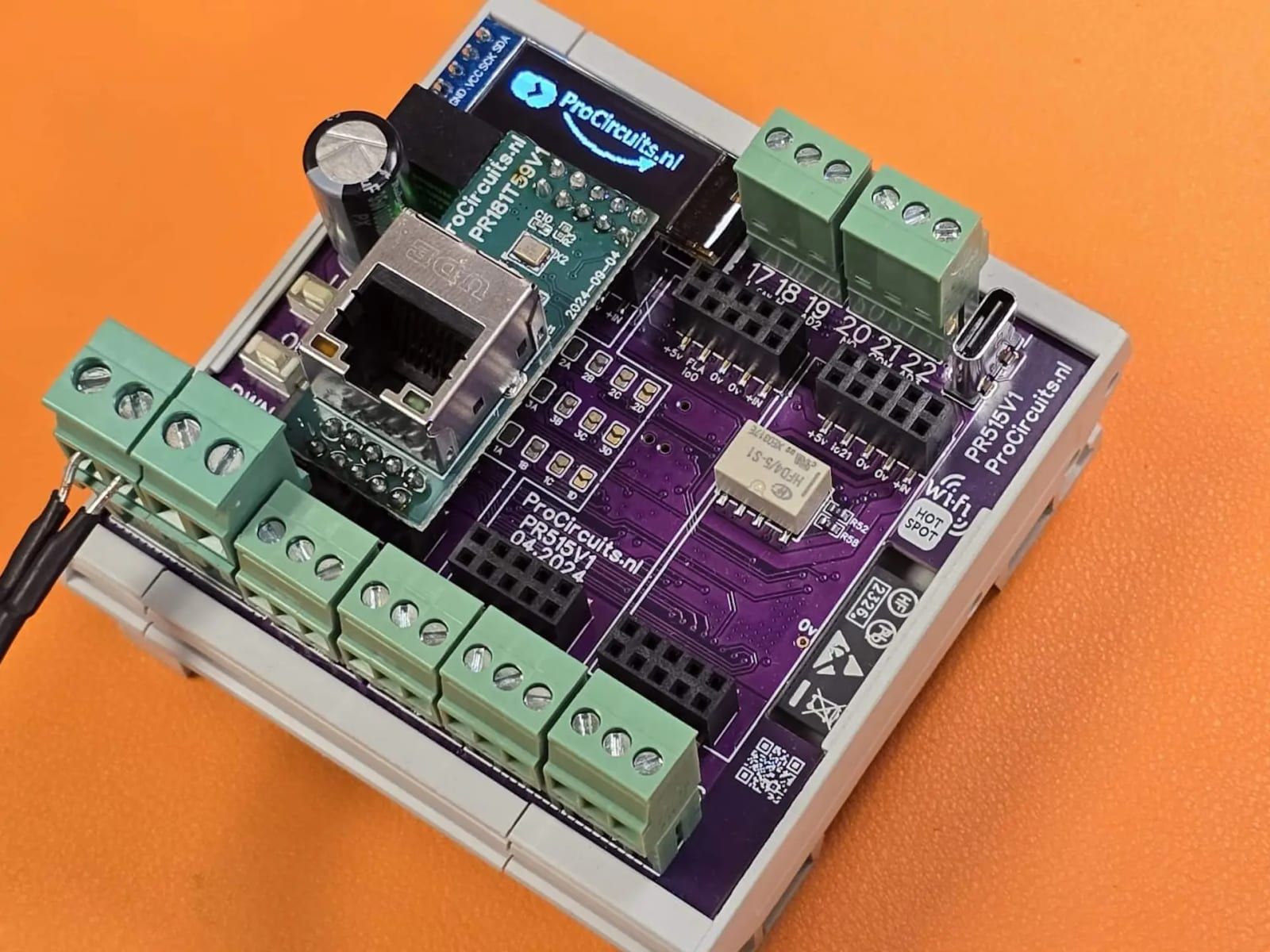
PR515x006
In: 0-10 VOut: 0-10 V
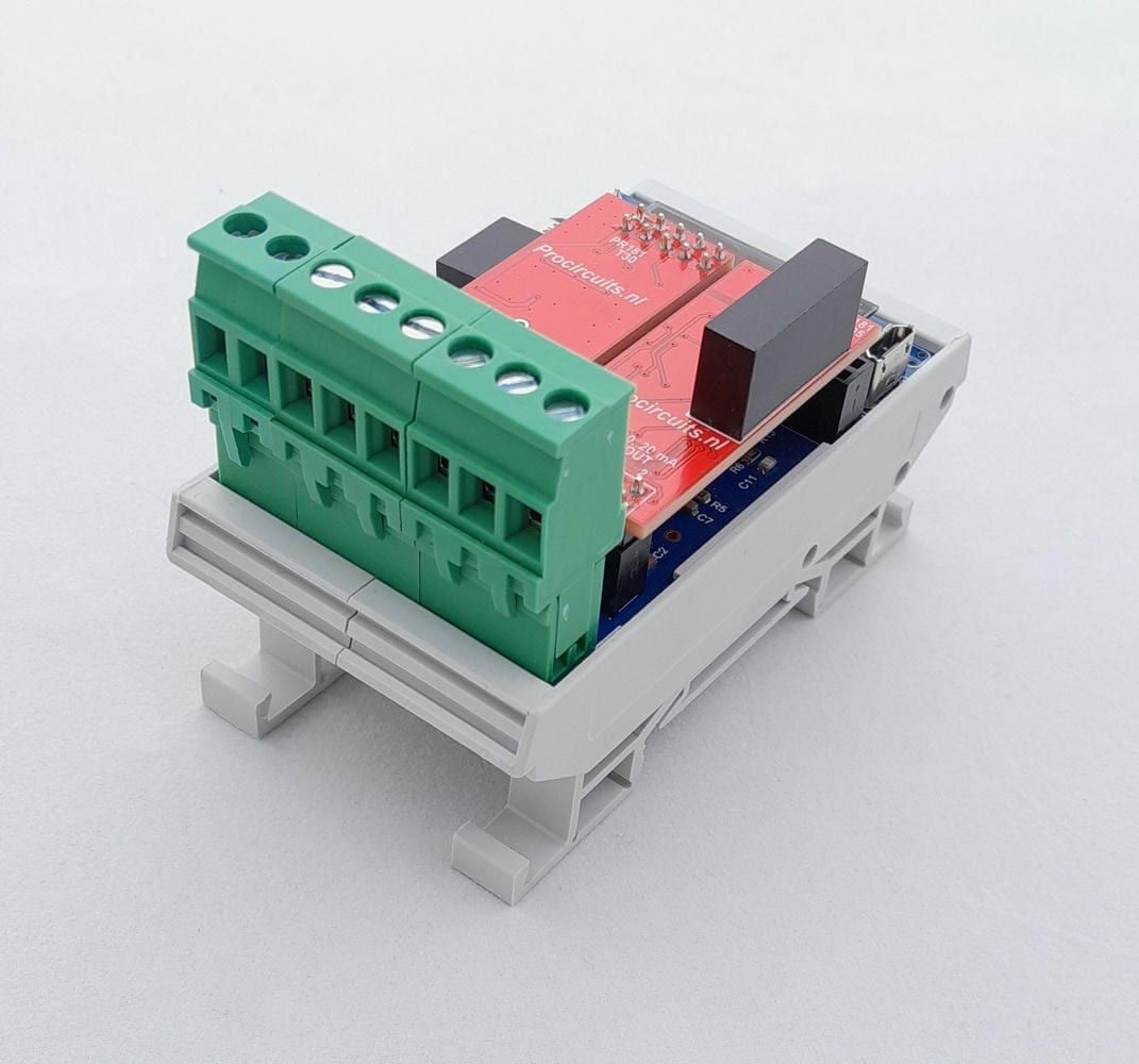
PR181-X046
In: Joystick or PotentiometerOut: 4-20 mA or 0-20 mA
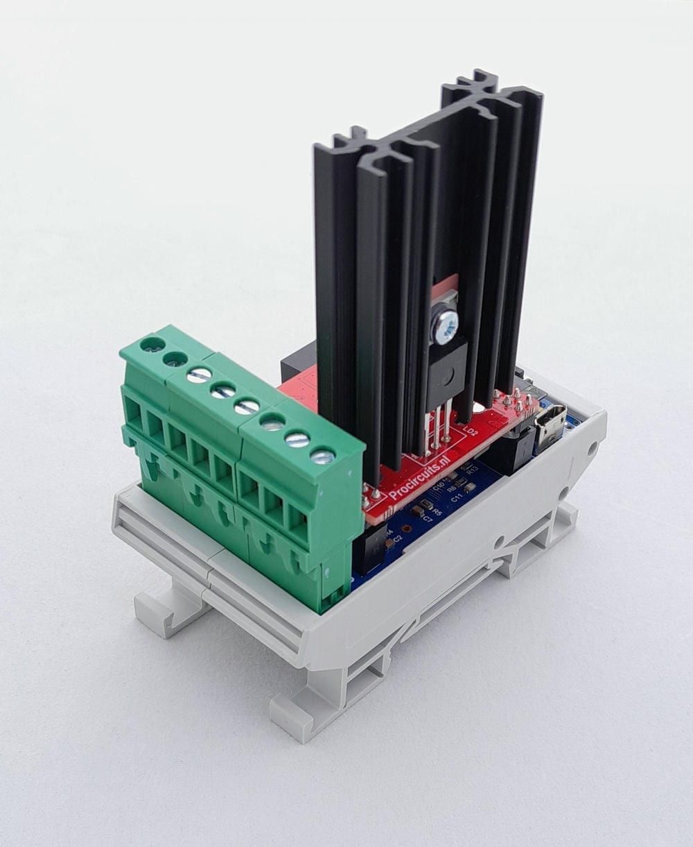
PR181-X052
In: Joystick or 0-10 VOut: PWM
PR159s25
In: ±10 VOut: PWM