Not quite right?
A different input, another range, galvanic isolation or your own logo: we adapt the module.


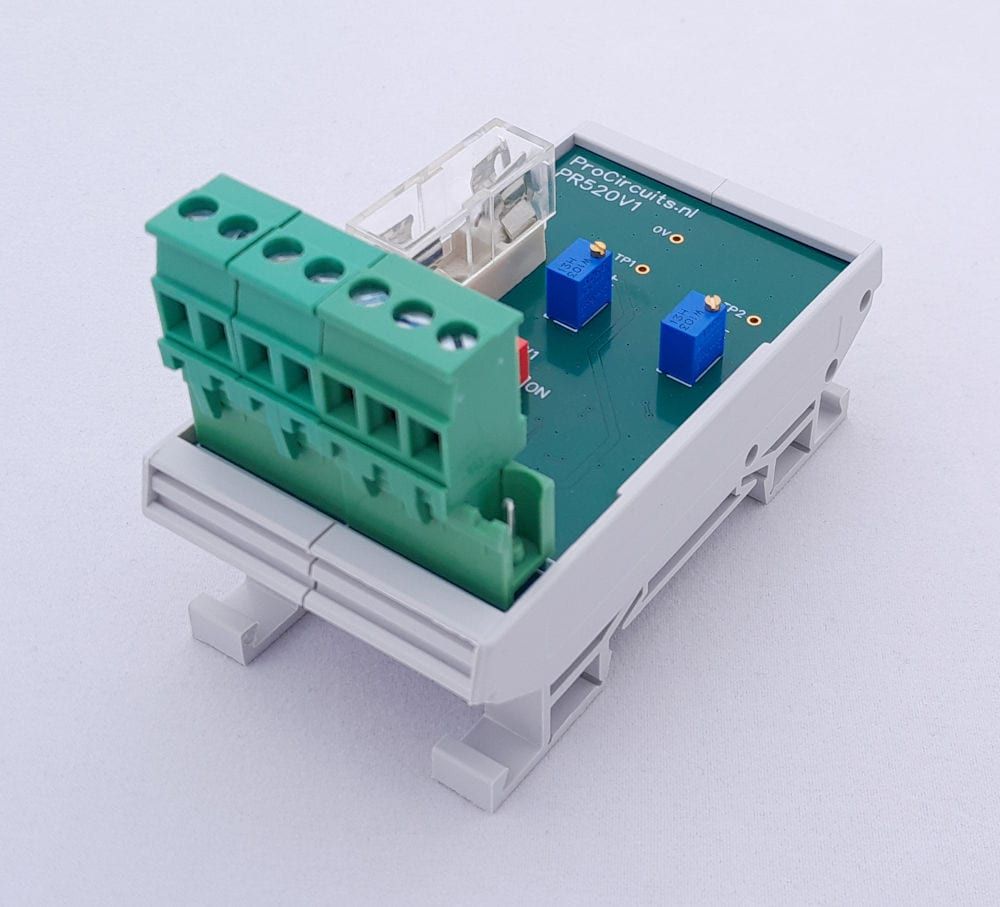
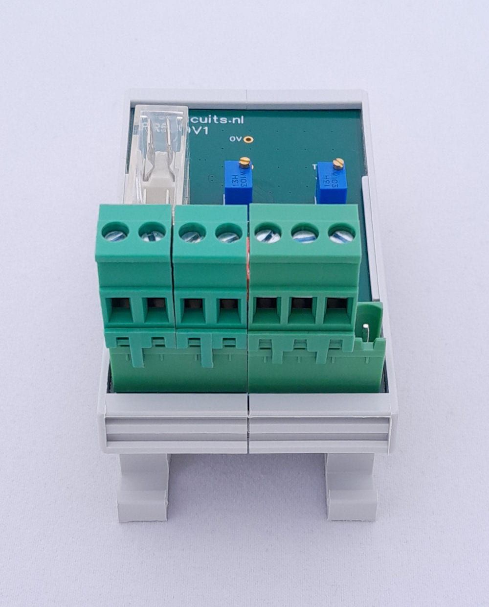
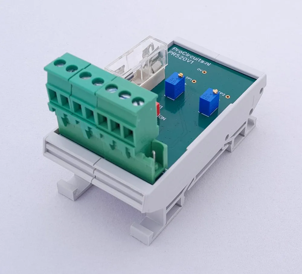
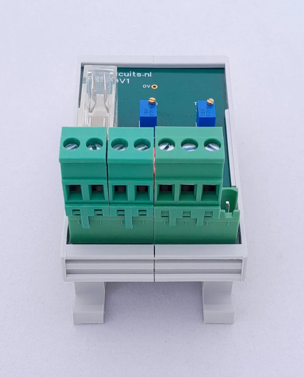
Article number PR520-X001
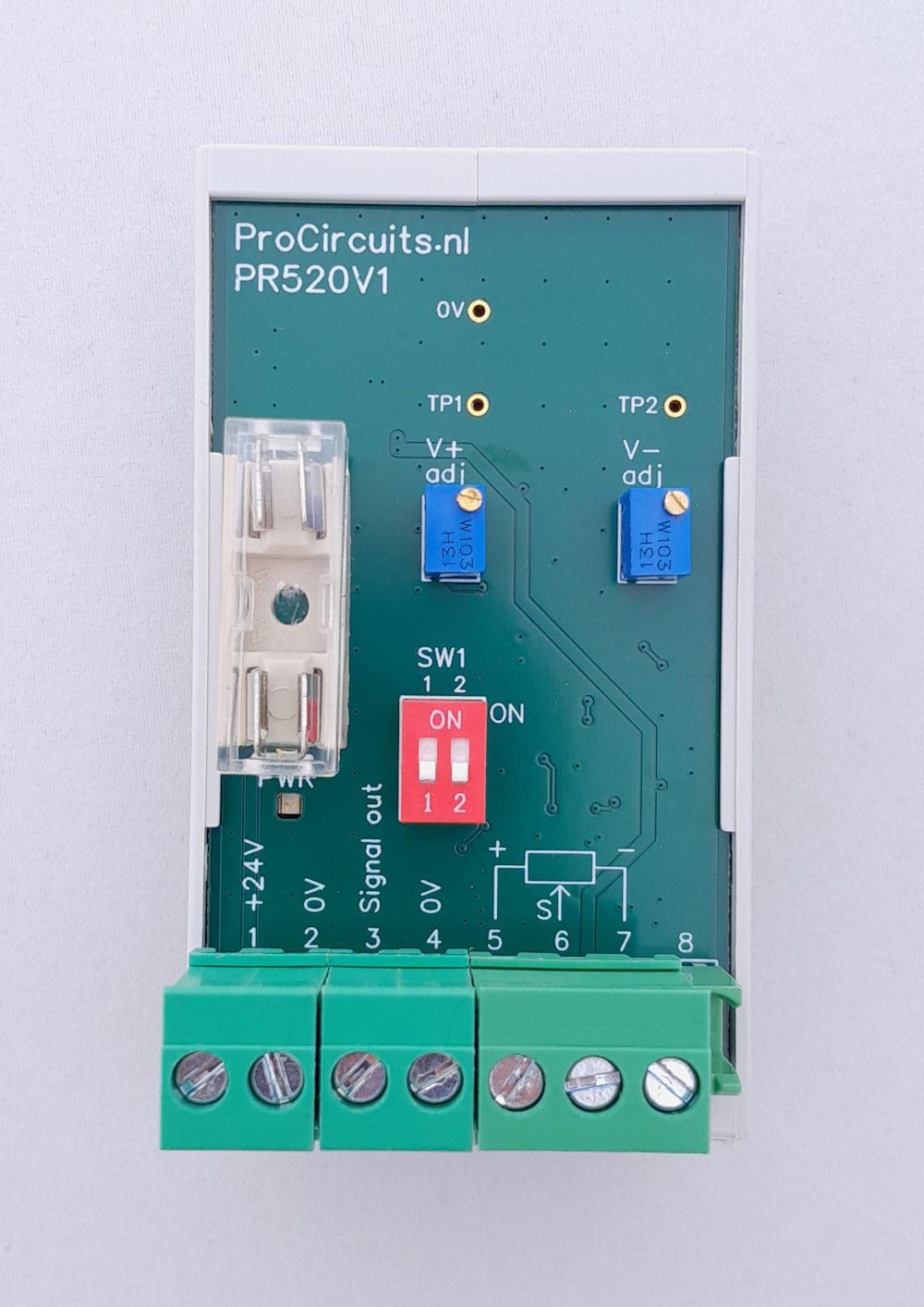
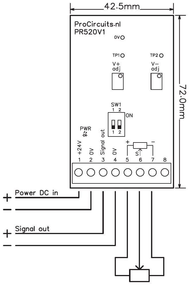
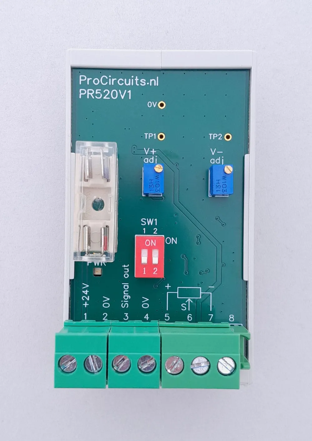
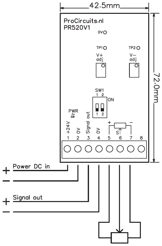
Potentiometers in control levers and joysticks are often connected between 0 and 5 V. The PR520-X001 adjusts that range when the device reading the potentiometer has no setting for it. The module supplies the potentiometer with an upper and lower limit, each set with a trimmer from 0 to 7 V, for example 1-5 V or 0.5-3 V, and passes the amplified potentiometer signal to the output. Supply, input and output are not galvanically isolated.
Price on request
Lead time on request. Not in stock? We will make it.
Orders are placed by email with a purchase order. We supply businesses only.
| Supply | 14 to 32 V DC |
|---|---|
| Input | Potentiometer, 1 kΩ to 100 kΩ, on terminals 5, 6 and 7 |
| Output | Amplified potentiometer signal on terminal 3; load 1 kΩ min., 200 pF max. |
| Isolation | Not isolated: supply, input and output are not galvanically isolated; terminal 4 is internally connected to terminal 2 |
| Setup | Trimmers V+ adj (upper limit) and V- adj (lower limit) |
| Potentiometer supply | Upper and lower limit each adjustable from 0 to 7 V; the lower limit can never exceed the upper limit |
| Dimensions | 45 x 83 mm with DIN rail enclosure, 42.5 x 72 mm without |
| Terminal | Function |
|---|---|
| Terminal 1 | Supply plus, +24 V |
| Terminal 2 | Supply 0 V |
| Terminal 3 | Signal output (plus) |
| Terminal 4 | Signal output 0 V, internally connected to terminal 2 |
| Terminal 5 | Potentiometer plus (upper limit) |
| Terminal 6 | Potentiometer signal (wiper) |
| Terminal 7 | Potentiometer minus (lower limit) |
| Terminal 8 | Not used |
A different input, another range, galvanic isolation or your own logo: we adapt the module.
You speak directly with the developer. Call or message Willem on +31 6 45 77 55 93.
PR520-X001
Enter the quantity. You will receive price and lead time by email. You then order with a purchase order.
Send the article number and quantity via WhatsApp to +31 6 83 66 55 88. Willem replies on working days.
WhatsApp Willem(opens in a new tab)Potentiometers
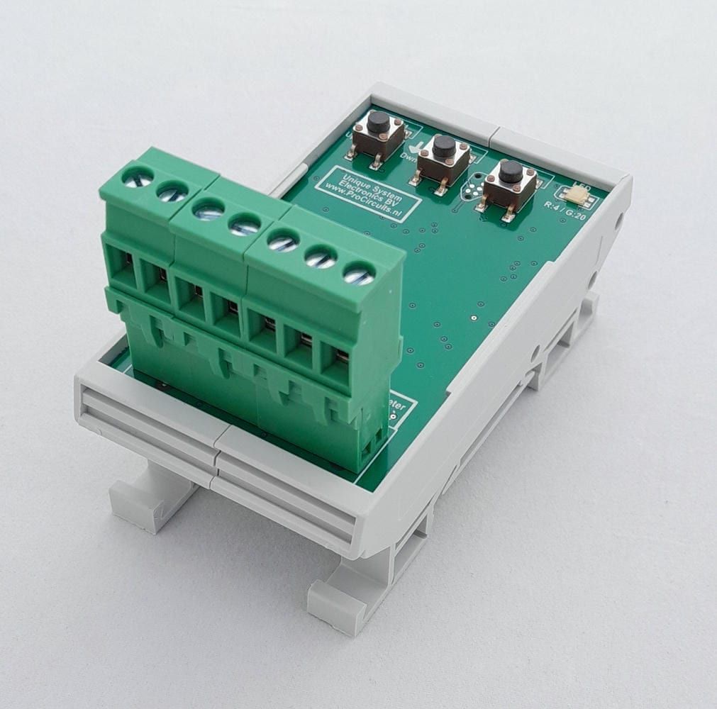
PR100s08
In: PotentiometerOut: 0-5 V
PR100s07
In: PotentiometerOut: 0-10 V
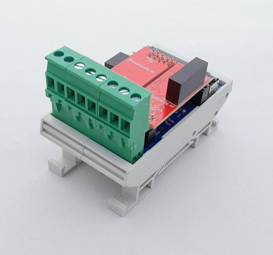
PR181-X067
In: PotentiometerOut: 0-10 V
PR181-X046
In: Joystick or PotentiometerOut: 4-20 mA or 0-20 mA