Not quite right?
A different input, another range, galvanic isolation or your own logo: we adapt the module.


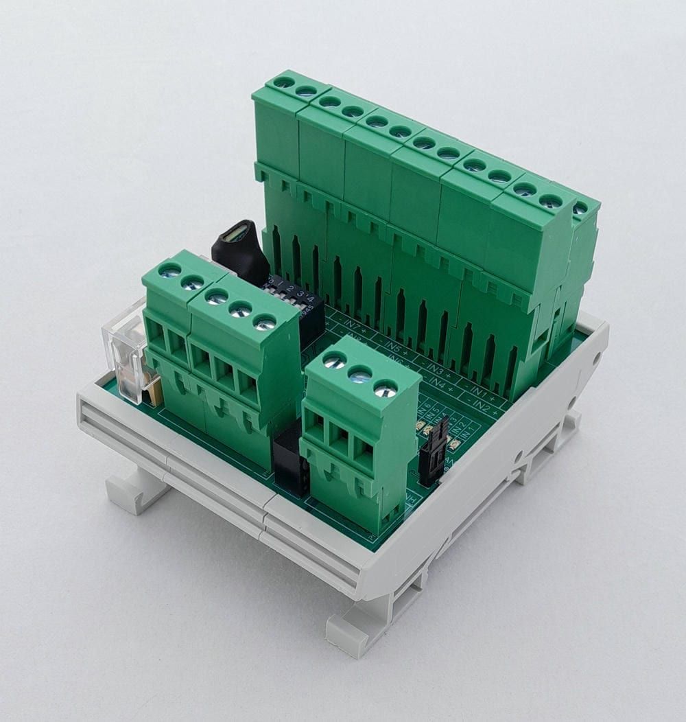
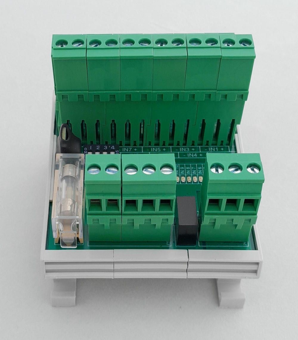
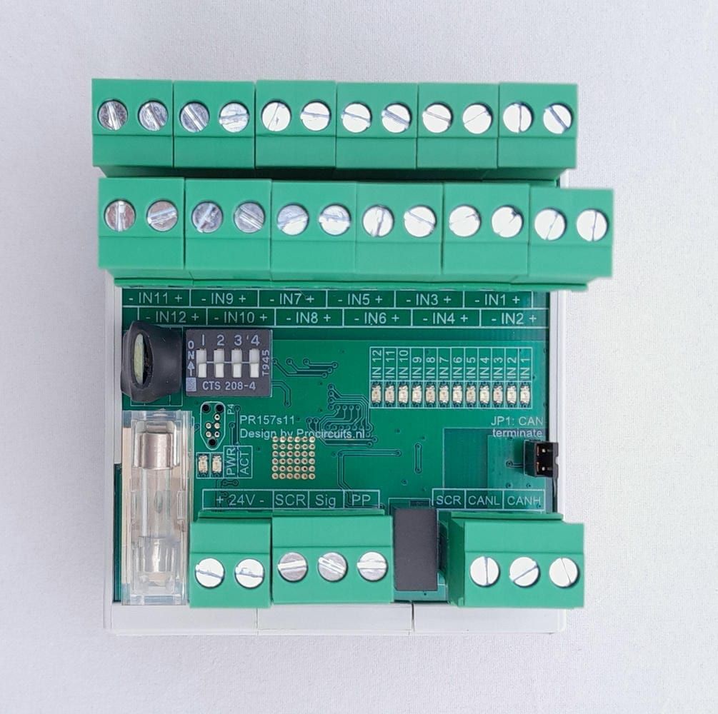
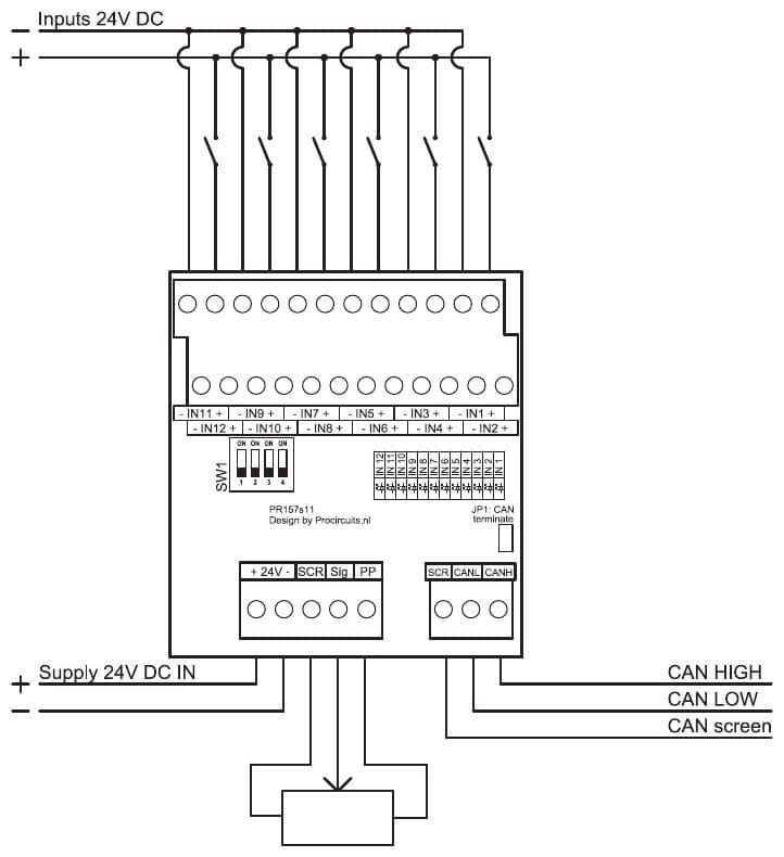
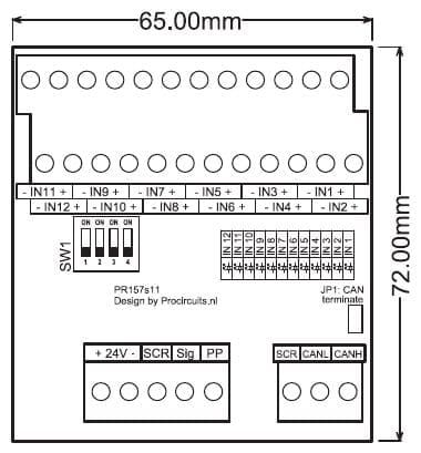
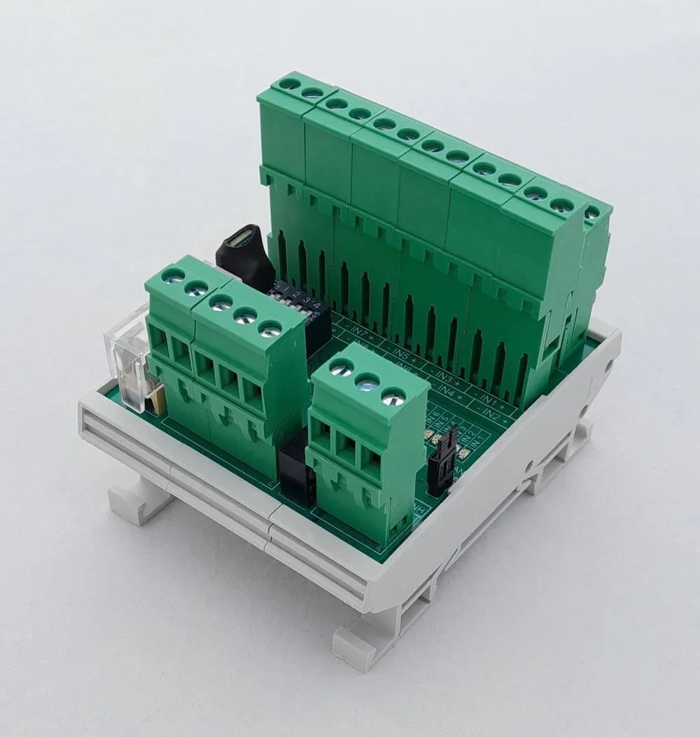
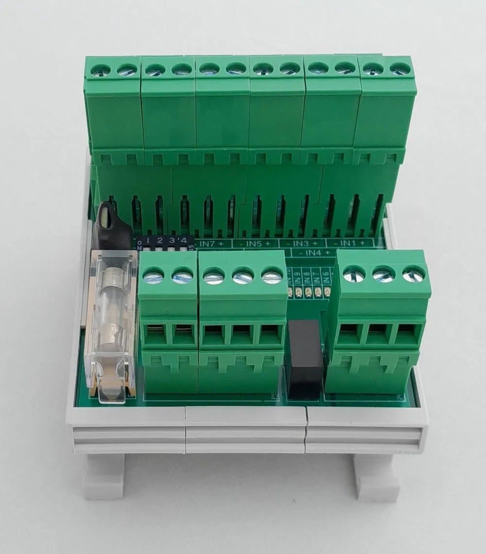
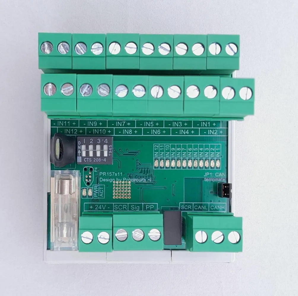
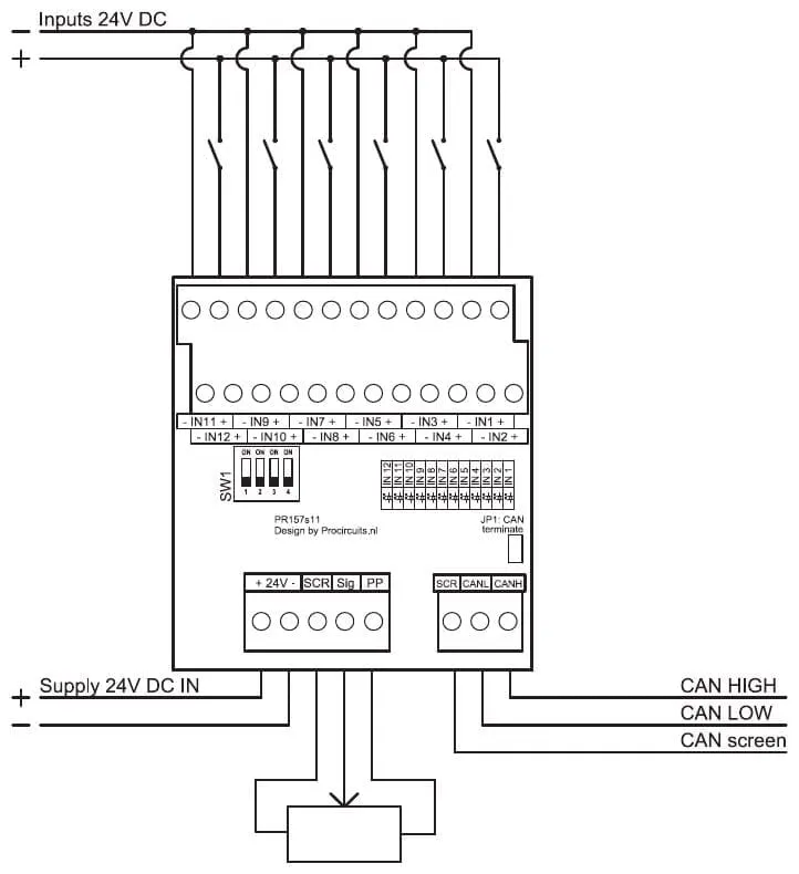
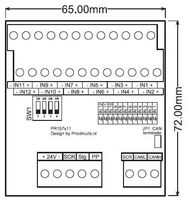
Article number PR157s11
The PR157s11 has twelve digital inputs and a potentiometer input. The inputs accept 24 V signals, each have their own plus and minus terminal and are optically isolated from the potentiometer input and the supply. The module runs on a 9 to 30 V DC supply.
Price on request
Lead time on request. Not in stock? We will make it.
Orders are placed by email with a purchase order. We supply businesses only.
| Supply | 9 to 30 V DC |
|---|---|
| Input | 12 digital inputs of 24 V DC, 6.7 mA per input at 24 V; potentiometer input for 1 kΩ to 100 kΩ |
| Isolation | Digital inputs optically isolated from the potentiometer input and the supply |
| Communication | CAN bus; 120 Ω termination enabled with jumper JP1 |
| Indication | Status LED per input; PWR and ACT LEDs |
| Dimensions | 68 x 83 mm with DIN rail enclosure, 65 x 72 mm without |
| Mounting | DIN rail |
| Terminal | Function |
|---|---|
| Terminal +24V | Supply plus |
| Terminal -24V | Supply minus (0 V) |
| Terminal SCR | Potentiometer minus |
| Terminal Sig | Potentiometer signal (wiper) |
| Terminal PP | Potentiometer plus |
| Terminal CAN SCR | CAN bus cable shield |
| Terminal CANL | CAN bus low |
| Terminal CANH | CAN bus high |
| Terminal IN1+ – IN12+ | Plus of input 1 to 12 (+24 V of the input signal) |
| Terminal IN1- – IN12- | Minus of input 1 to 12 |
The PR157 series consists of DIN rail modules. The CAN bus versions read optically isolated 24 V inputs and a potentiometer, or switch relay outputs (24 V DC, 5 A) with separate NO, COM and NC terminals per output; status LEDs show the state of each input or output. Terminate both ends of the CAN bus network with 120 Ω: fit jumper JP1 on the module at the end of the network. More inputs or outputs, or control via RS485 and Modbus instead of CAN bus, are available on request for these versions.
A different input, another range, galvanic isolation or your own logo: we adapt the module.
You speak directly with the developer. Call or message Willem on +31 6 45 77 55 93.
PR157s11
Enter the quantity. You will receive price and lead time by email. You then order with a purchase order.
Send the article number and quantity via WhatsApp to +31 6 83 66 55 88. Willem replies on working days.
WhatsApp Willem(opens in a new tab)I/O modules
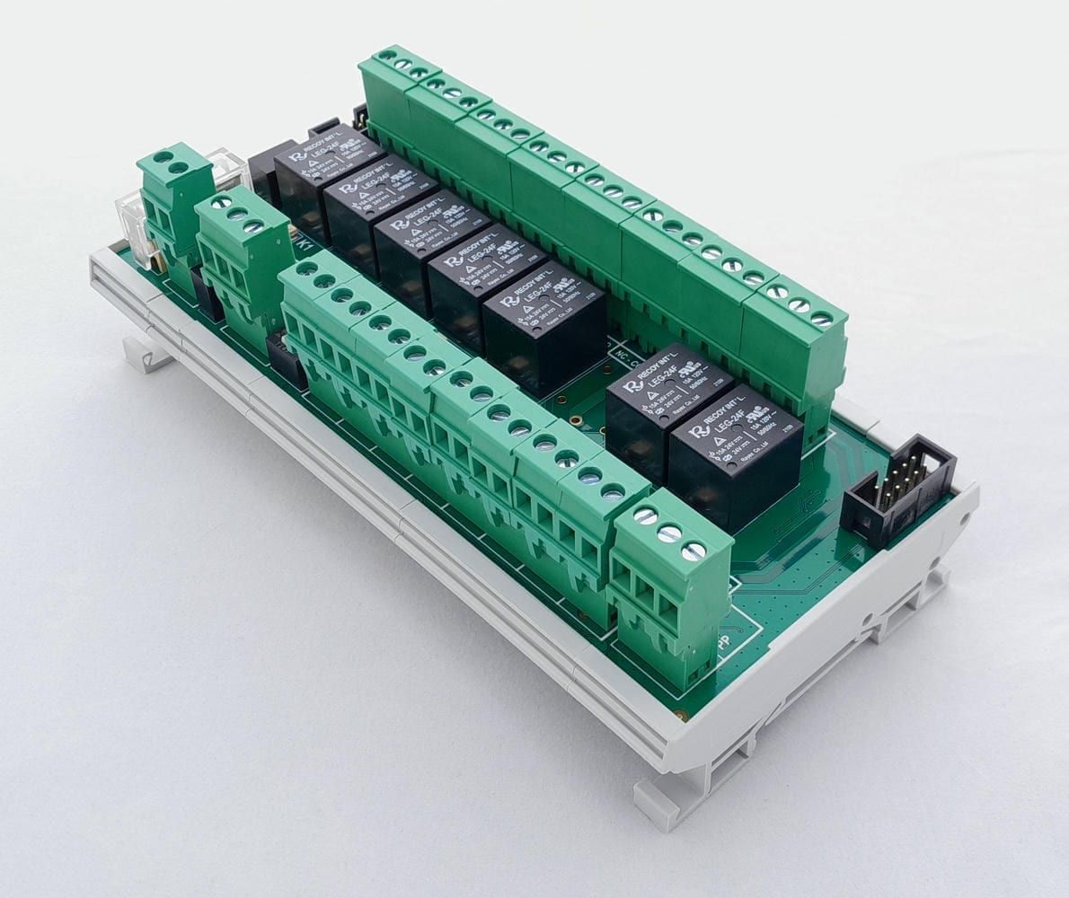
PR157s08
In: Digital, Potentiometer or CANOut: Relay or CAN
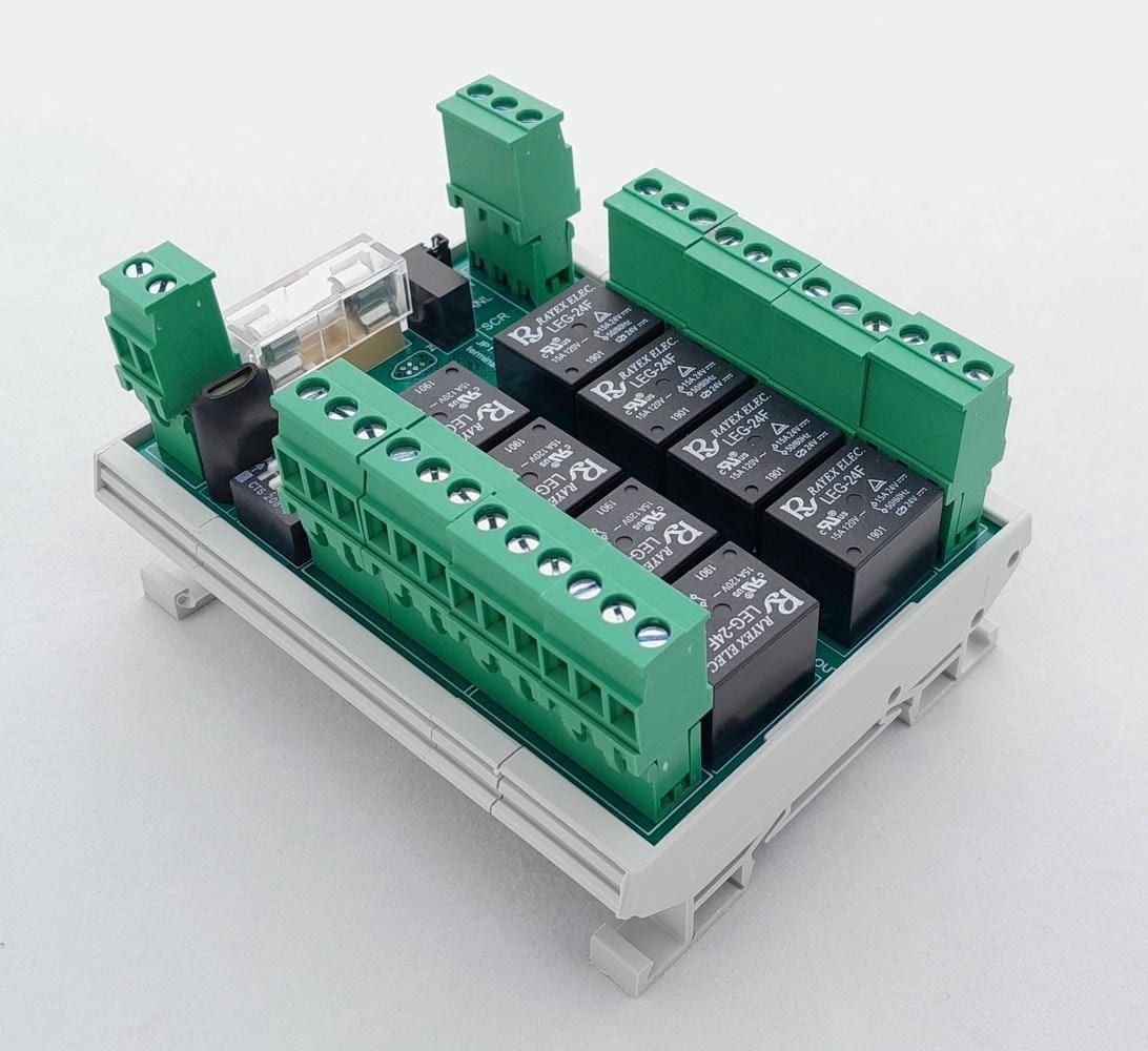
PR157s12
In: CANOut: Relay
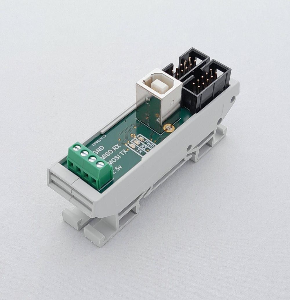
PR157s05
In: USB
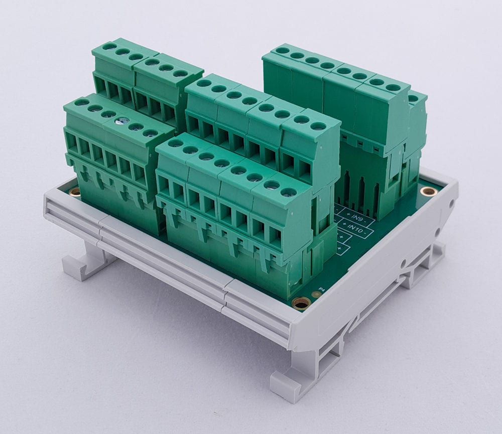
PR131s01
In: 0-10 V, 4-20 mA, Resistance, Potentiometer or DigitalOut: Modbus